
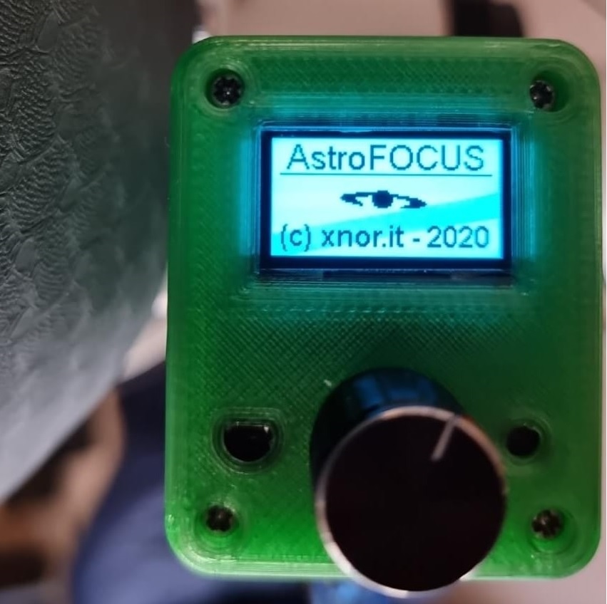
This project started in 2017 when me, Vittorio, decided to practice a new hobby … Astronomical photography. After in-depth studies on Internet, I bought my first telescope and the related equipment.
Step by step I became familiar with this fantastic hobby and above all I began to understand the need to automate some processes. One of them is telescope focusing.
In recent years have been released programs dedicated to Astrophotography which allow, with the addition of an electronic focuser, to control the focus of the telescope during a photographic session.
The electronic focuser is an object that mechanically connected to the telescope focuser pinion allows it to be rotated back and forth (even by hundredths of a degree) through commands sent from the computer through a serial port (USB). This means that with the help of specific drivers (in my case ASCOM) the program is able to control the focus of the telescope.
Having seen the various focusers on the market, I made the decision to design and build my own Astronomy FOCUS.
The Project
The first thing to do in a project is the list of features:
– Simple hardware based on Arduino
– C Programming language
– Avoid using third party Arduino libraries.
– Presence of a display and an encoder to control the focus even without using a PC (optional)
– Temperature sensor (optional)
– Compatibility with 2-phase bipolar stepper motors
– 12V DC power supply
– Serial port via USB
– ASCOM driver
This project is not difficult and is suitable for anyone who is familiar with Arduino, electronics, soldering iron and programming. For this, we will not go into too much detail of the construction.
PLEASE if you’re not expert or confident with electronics, or if you’re a minor, seek for help from an experienced adult. This is not a dangerous project but something can always go wrong. Please read also che disclaimer at the end of this page.
Hardware
In this section we will show the most important hardware parts used in this project and the wiring diagram.
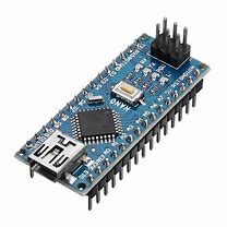
As microcontroller I have chosen the Arduino NANO or compatible board.
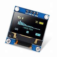
The display is the classic 128×64 I2C OLED. This display is available in various colours (white, blue, yellow, blue-yellow).
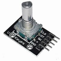
The encoder is the model with push button switch
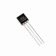
The temperature sensor is the Dallas 18B20
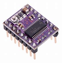
The driver for the stepper motor is the Pololu DRV8825 Stepper Motor Driver for 3d Printer or equivalent
Classic standard electronic components (resistors, capacitors, connectors, etc) are required.
Wiring Diagram
We have two types of wiring diagrams. The first is more complex and include all parts, while, the second is more simple and doesn’t include encoder and display.
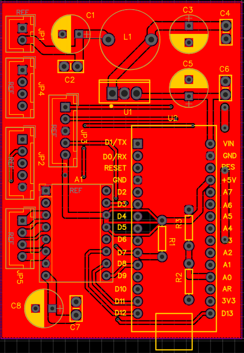
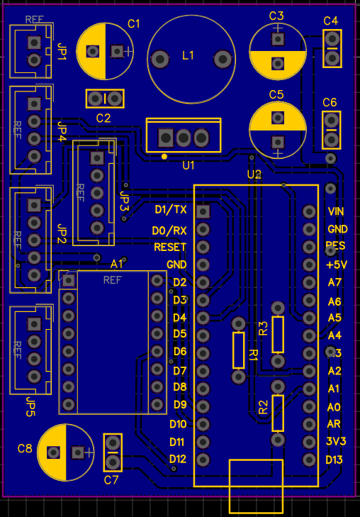
PCB Board
Here you can find all Gerber file for build your prototype of PCB for wiring diagram type 1
Stepper Motor
The stepper motor driver is capable of driving up to 2.5 A of current from each output (with proper heat sinking, at 24 V and 25°C) but the current sense resistors further limit the maximum current to 2.2 A. This allows us to use a wide range of two-phase stepper motors. Feel free to choose the model that best suits your focuser, but our suggestion is not to exceed 1.5 Amps per phase with this stepper driver.
In our project we chose the 8HS15-0604S-PG64 stepper motor that it is available on www.omc-stepperonline.com.
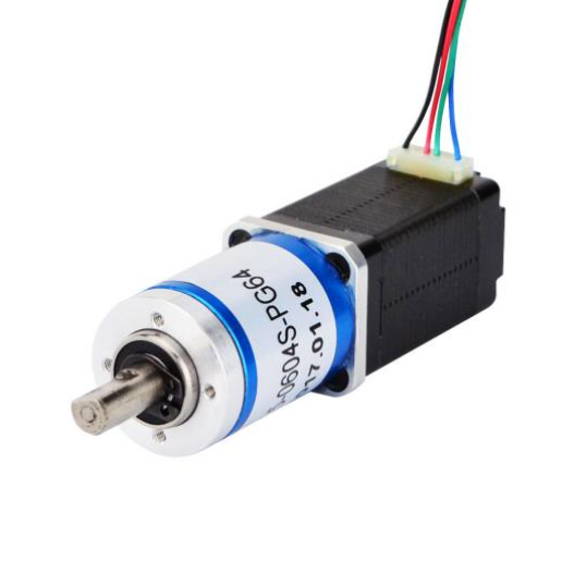
This is a Nema 8 stepper motor with 38mm body and 0.6A rated current, It is integrated with a planetary gearbox of 64:1 gear ratio. As mentioned on the seller’s site, It’s a good solution to applications that with limited space but need low speed and/or high torque. Below are the characteristics of this stepper motor:
Electrical Specification
– Manufacturer Part Number: 8HS15-0604S-PG64
– Motor Type: Bipolar Stepper
– Step Angle: 0.028 deg
– Holding Torque without Gearbox: 4Ncm(5.66oz.in)
– Rated Current/phase: 0.6A
– Phase Resistance: 11ohms
– Voltage: 6V
– Inductance: 5.5mH ± 20%(1KHz)
Gearbox Specifications
– Gearbox Type: Planetary
– Gear Ratio: 64: 1
– Efficiency: 73%
– Backlash at No-load: <=1 deg
– Max. Permissible Torque: 0.9Nm(127.5oz.in)
– Moment Permissible Torque: 2Nm(283oz.in)
– Shaft Maximum Axial Load: 5N
– Shaft Maximum Radial Load: 25N
The full datasheet is available on http://www.omc-stepperonline.com/
Stepper motor driver current setting
One of the important topics is the adjustment of the current driving the stepper motors. Our approach is tune the current with the potentiometer on the DRV8825 driver board by measuring the reference voltage of the driver circuit. The driver circuit adjusts automatically the motor current based on voltage at the reference input.
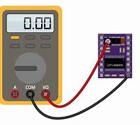
Pololu describes on their website, that the relationship between the stepper motor current and reference voltage is expressed with the following equation:
Current Limit = VREF × 2
That means, if the DRV8825 shall drive the stepper motor with 0.6A the reference voltage has to be adjusted to 0.3V.
This equation is only true if the sense resistor on the driver has a value of 100 milliOhm.
Before using this formula it is always necessary to check what is reported by the driver supplier regarding the adjustment of the driving current.
Software
The firmware was entirely written from scratch in collaboration with my friend Giuliano and does not use third-party libraries to drive the display, encoder and temperature sensor.
Since we wrote this code for the purpose of sharing and not selling, you can use this software only for your personal use and not for commercial use.
The source is quite commented but for any info you can contact me.
We use interrupts to manage the encoder and the stepper motor.
The Serial port, configured at 9600 8 N 1, is used to communicate with ASCOM driver with the following commands:
SED# Reply: [none] “Set. EEprom default”
FSDn# Reply: 0# or 1# “Set Focuser Motor direction”
FSMn# Reply: [none] “Set Focuser Max Position”
FSSn.n# Reply: [none] “Set Focuser Scale”
GIP# Reply: AstroFocus# “Get. Info. Product”
GIN# Reply: 1.0.a# “Get. Info. Firmware version”
FGD# Reply: 0# or #1 “Get Motor direction”
FGM# Reply: M# or S# “Get Focuser status”
FGO# Reply: n# “Get Focuser Max out position”
FGP# Reply: n# “Get Focuser Position”
FGS# Reply: n.n# “Get Focuser Scale”
FGT# Reply: n.n# “Get Focuser temperature”
FSH# Reply: [none] “Halt Fouser”
FSAn# Reply: [none] “Move Focuser to Absolute position”
FSC# Reply: [none] “Store Focuser Current Position in EEpro
Here you can find there the source code of the entire project. The code can be used “as is” and compiled on Arduino IDE or Visual Studio Code with Platformio. You can exclude the support of display-encoder and temperature sensor commenting the following define:
#define ENCODER_DISPLAY
#define TEMPERATURE_SENSOR
Remember
This program is free software; you can redistribute it and/or modify it under the terms of the GNU General Public License as published by the Free Software Foundation; either version 2 of the License, or (at your option) any later version.
This program is distributed in the hope that it will be useful,but WITHOUT ANY WARRANTY; without even the implied warranty of MERCHANTABILITY or FITNESS FOR A PARTICULAR PURPOSE. See the GNU General Public License for more details.
You should have received a copy of the GNU General Public License along with this program; if not, write to the Free Software Foundation, Inc., 59 Temple Place, Suite 330, Boston, MA 02111-1307 USA
/********************************************************************************
*
* Astronomy FOCUSER - Version 1.0.a
*
*
* A project done with Arduino IDE in 2020 by:
* Giuliano C. Peritore (bugtimizer) - g.peritore@xnor.it
* Vittorio Signorelli (spiman) - v.signorelli@xnor.it
*
*
* This program is free software; you can redistribute it and/or modify
* it under the terms of the GNU General Public License as published by
* the Free Software Foundation; either version 2 of the License, or
* (at your option) any later version.
*
* This program is distributed in the hope that it will be useful,
* but WITHOUT ANY WARRANTY; without even the implied warranty of
* MERCHANTABILITY or FITNESS FOR A PARTICULAR PURPOSE. See the
* GNU General Public License for more details.
*
* You should have received a copy of the GNU General Public License
* along with this program; if not, write to the Free Software
* Foundation, Inc., 59 Temple Place, Suite 330, Boston, MA 02111-1307 USA
*
*******************************************************************************/
#include <Arduino.h>
#include <EEPROM.h>
#include <Wire.h>
#include <stdio.h>
#include <math.h>
#include <string.h>
#include <float.h>
// Debug
//#define DEBUG_TRACE
#define ENCODER_DISPLAY
#define TEMPERATURE_SENSOR
// Global definitions
#define AstroFocusName "AstroFOCUS"
#define AstroRelease "1.0.a"
#define FOCUSER_MAX_POSITION 1000000
#define FOCUSER_DEFAULT_MICRON 1.31
#define FOCUSER_DEFAULT_DIRECTION false;
#define SERIAL_BUFFER 10
// Stepper Motor Driver
#define STEPPER_M0 11
#define STEPPER_M1 12
#define STEPPER_M2 13
#define STEPPER_EN 8
#define STEPPER_STEP 9
#define STEPPER_DIR 10
#define STEPPER_END_STOP A1
#define MOTOR_MAX_RATE 1999 // = (16*10^6) / (1000*8) - 1 (must be <65536)
#define STEPPER_ENABLED LOW
#define STEPPER_DISABLED HIGH
#define STEPPER_DRIVE_ENABLE_WAIT_TIME 5
// Temperature Sensor DS18B20
#define DS18B20_DATA 7
//Encoder
#define ENCODER_CLK 3
#define ENCODER_DATA 2
#define ENCODER_SW 4
// EEPROM
#define EEPROM_KEY_0 0x00
#define EEPROM_KEY_1 0x01
#define EEPROM_KEY_2 0x02
#define EEPROM_MOTOR_DIRECTION 0x10
#define EEPROM_CURRENT_POSITION 0x20
#define EEPROM_MAX_POSITION 0x24
#define EEPROM_STEP_MICRON 0x28
#define EEPROM_MOVE_WAIT_TIME 300
// OLED Display SSD1306
#define SSD1306_ADDRESS 0x3C
#define SSD1306_COMMAND 0x00
#define SSD1306_DATA 0x40
#define SSD1306_LCDWIDTH 128
#define SSD1306_LCDHEIGHT 64
#define SSD1306_SETCONTRAST 0x81
#define SSD1306_DISPLAYALLON_RESUME 0xA4
#define SSD1306_DISPLAYALLON 0xA5
#define SSD1306_NORMALDISPLAY 0xA6
#define SSD1306_INVERTDISPLAY 0xA7
#define SSD1306_DISPLAYOFF 0xAE
#define SSD1306_DISPLAYON 0xAF
#define SSD1306_SETDISPLAYOFFSET 0xD3
#define SSD1306_SETCOMPINS 0xDA
#define SSD1306_SETVCOMDETECT 0xDB
#define SSD1306_SETDISPLAYCLOCKDIV 0xD5
#define SSD1306_SETPRECHARGE 0xD9
#define SSD1306_SETMULTIPLEX 0xA8
#define SSD1306_SETLOWCOLUMN 0x00
#define SSD1306_SETHIGHCOLUMN 0x10
#define SSD1306_SETSTARTLINE 0x40
#define SSD1306_MEMORYMODE 0x20
#define SSD1306_COLUMNADDR 0x21
#define SSD1306_PAGEADDR 0x22
#define SSD1306_COMSCANINC 0xC0
#define SSD1306_COMSCANDEC 0xC8
#define SSD1306_SEGREMAP 0xA0
#define SSD1306_CHARGEPUMP 0x8D
#define SSD1306_SETSTARTPAGE 0xB0
#define PIXEL_W 128
#define PIXEL_H 64
#define PIXEL_COL_START 0
#define BLACK 0
#define WHITE 1
#define INVERSE 2
// Scrolling #defines
#define SCROLL_RIGTH 1
#define SCROLL_LEFT 1
#define SSD1306_ACTIVATE_SCROLL 0x2F
#define SSD1306_DEACTIVATE_SCROLL 0x2E
#define SSD1306_SET_VERTICAL_SCROLL_AREA 0xA3
#define SSD1306_RIGHT_HORIZONTAL_SCROLL 0x26
#define SSD1306_LEFT_HORIZONTAL_SCROLL 0x27
#define SSD1306_VERTICAL_AND_RIGHT_HORIZONTAL_SCROLL 0x29
#define SSD1306_VERTICAL_AND_LEFT_HORIZONTAL_SCROLL 0x2A
#define swap_int16_t(a, b) { int16_t t = a; a = b; b = t; }
//Global variables
// Memory buffer for the Display
uint8_t display_buffer[1024];
// Encoder
volatile int8_t lastEncoded = 0;
volatile int32_t encoderValue = 0;
int8_t encoderTasto = 0;
int32_t encoderOldValue = 0;
bool encoderEnable = true;
int32_t encoderRealValue;
// Current screen
uint8_t screen = 0;
uint8_t screenTime = 0;
// Timers
uint8_t oneSecondTimer = 0;
uint8_t oneSecondSensorTimer = 0;
uint16_t oneSecondEEpromTimer = 0;
uint16_t oneSecondStepperEnableTimer = 0;
uint32_t lastMillisecond;
// Focuser
bool focuserIsMoving = false;
bool focuserMotorDirection = false;
bool focuserDriverOff = true;
bool focuserSaveEEprom = false;
int32_t focuserCurrentPosition = 0;
int32_t focuserMoveToTarget = 0;
int32_t focuserMaxPosition = FOCUSER_MAX_POSITION;
float focuserMicronsPerStep = FOCUSER_DEFAULT_MICRON;
float focuserTemperature = 10.0;
char SerialBuffer[SERIAL_BUFFER];
int16_t stepMultiplierArray[] = {1,5,10,100,1000,0,0};
int8_t stepMultiplier = 0;
//*****************************************************************************
// A 5x7 font (in a 6x8 cell, where the sixth column is omitted from this
// table) for displaying text on the OLED display. The data is organized as
// bytes from the left column to the right column, with each byte containing
// the top row in the LSB and the bottom row in the MSB.
//*****************************************************************************
const PROGMEM uint8_t Font[] =
{
0x00, 0x00, 0x00, 0x00, 0x00, 0x00 , // " "
0x00, 0x00, 0x00, 0x4f, 0x00, 0x00 , // !
0x00, 0x00, 0x07, 0x00, 0x07, 0x00 , // "
0x00, 0x14, 0x7f, 0x14, 0x7f, 0x14 , // #
0x00, 0x24, 0x2a, 0x7f, 0x2a, 0x12 , // $
0x00, 0x23, 0x13, 0x08, 0x64, 0x62 , // %
0x00, 0x36, 0x49, 0x55, 0x22, 0x50 , // &
0x00, 0x00, 0x05, 0x03, 0x00, 0x00 , // '
0x00, 0x00, 0x1c, 0x22, 0x41, 0x00 , // (
0x00, 0x00, 0x41, 0x22, 0x1c, 0x00 , // )
0x00, 0x14, 0x08, 0x3e, 0x08, 0x14 , // *
0x00, 0x08, 0x08, 0x3e, 0x08, 0x08 , // +
0x00, 0x00, 0x50, 0x30, 0x00, 0x00 , // ,
0x00, 0x08, 0x08, 0x08, 0x08, 0x08 , // -
0x00, 0x00, 0x60, 0x60, 0x00, 0x00 , // .
0x00, 0x20, 0x10, 0x08, 0x04, 0x02 , // /
0x00, 0x3e, 0x51, 0x49, 0x45, 0x3e , // 0
0x00, 0x00, 0x42, 0x7f, 0x40, 0x00 , // 1
0x00, 0x42, 0x61, 0x51, 0x49, 0x46 , // 2
0x00, 0x21, 0x41, 0x45, 0x4b, 0x31 , // 3
0x00, 0x18, 0x14, 0x12, 0x7f, 0x10 , // 4
0x00, 0x27, 0x45, 0x45, 0x45, 0x39 , // 5
0x00, 0x3c, 0x4a, 0x49, 0x49, 0x30 , // 6
0x00, 0x01, 0x71, 0x09, 0x05, 0x03 , // 7
0x00, 0x36, 0x49, 0x49, 0x49, 0x36 , // 8
0x00, 0x06, 0x49, 0x49, 0x29, 0x1e , // 9
0x00, 0x00, 0x36, 0x36, 0x00, 0x00 , // :
0x00, 0x00, 0x56, 0x36, 0x00, 0x00 , // ;
0x00, 0x08, 0x14, 0x22, 0x41, 0x00 , // <
0x00, 0x14, 0x14, 0x14, 0x14, 0x14 , // =
0x00, 0x00, 0x41, 0x22, 0x14, 0x08 , // >
0x00, 0x02, 0x01, 0x51, 0x09, 0x06 , // ?
0x00, 0x32, 0x49, 0x79, 0x41, 0x3e , // @
0x00, 0x7e, 0x11, 0x11, 0x11, 0x7e , // A
0x00, 0x7f, 0x49, 0x49, 0x49, 0x36 , // B
0x00, 0x3e, 0x41, 0x41, 0x41, 0x22 , // C
0x00, 0x7f, 0x41, 0x41, 0x22, 0x1c , // D
0x00, 0x7f, 0x49, 0x49, 0x49, 0x41 , // E
0x00, 0x7f, 0x09, 0x09, 0x09, 0x01 , // F
0x00, 0x3e, 0x41, 0x49, 0x49, 0x7a , // G
0x00, 0x7f, 0x08, 0x08, 0x08, 0x7f , // H
0x00, 0x00, 0x41, 0x7f, 0x41, 0x00 , // I
0x00, 0x20, 0x40, 0x41, 0x3f, 0x01 , // J
0x00, 0x7f, 0x08, 0x14, 0x22, 0x41 , // K
0x00, 0x7f, 0x40, 0x40, 0x40, 0x40 , // L
0x00, 0x7f, 0x02, 0x0c, 0x02, 0x7f , // M
0x00, 0x7f, 0x04, 0x08, 0x10, 0x7f , // N
0x00, 0x3e, 0x41, 0x41, 0x41, 0x3e , // O
0x00, 0x7f, 0x09, 0x09, 0x09, 0x06 , // P
0x00, 0x3e, 0x41, 0x51, 0x21, 0x5e , // Q
0x00, 0x7f, 0x09, 0x19, 0x29, 0x46 , // R
0x00, 0x46, 0x49, 0x49, 0x49, 0x31 , // S
0x00, 0x01, 0x01, 0x7f, 0x01, 0x01 , // T
0x00, 0x3f, 0x40, 0x40, 0x40, 0x3f , // U
0x00, 0x1f, 0x20, 0x40, 0x20, 0x1f , // V
0x00, 0x3f, 0x40, 0x38, 0x40, 0x3f , // W
0x00, 0x63, 0x14, 0x08, 0x14, 0x63 , // X
0x00, 0x07, 0x08, 0x70, 0x08, 0x07 , // Y
0x00, 0x61, 0x51, 0x49, 0x45, 0x43 , // Z
0x00, 0x00, 0x7f, 0x41, 0x41, 0x00 , // [
0x00, 0x02, 0x04, 0x08, 0x10, 0x20 , // "\"
0x00, 0x00, 0x41, 0x41, 0x7f, 0x00 , // ]
0x00, 0x04, 0x02, 0x01, 0x02, 0x04 , // ^
0x00, 0x40, 0x40, 0x40, 0x40, 0x40 , // _
0x00, 0x00, 0x01, 0x02, 0x04, 0x00 , // `
0x00, 0x20, 0x54, 0x54, 0x54, 0x78 , // a
0x00, 0x7f, 0x48, 0x44, 0x44, 0x38 , // b
0x00, 0x38, 0x44, 0x44, 0x44, 0x20 , // c
0x00, 0x38, 0x44, 0x44, 0x48, 0x7f , // d
0x00, 0x38, 0x54, 0x54, 0x54, 0x18 , // e
0x00, 0x08, 0x7e, 0x09, 0x01, 0x02 , // f
0x00, 0x0c, 0x52, 0x52, 0x52, 0x3e , // g
0x00, 0x7f, 0x08, 0x04, 0x04, 0x78 , // h
0x00, 0x00, 0x44, 0x7d, 0x40, 0x00 , // i
0x00, 0x20, 0x40, 0x44, 0x3d, 0x00 , // j
0x00, 0x7f, 0x10, 0x28, 0x44, 0x00 , // k
0x00, 0x00, 0x41, 0x7f, 0x40, 0x00 , // l
0x00, 0x7c, 0x04, 0x18, 0x04, 0x78 , // m
0x00, 0x7c, 0x08, 0x04, 0x04, 0x78 , // n
0x00, 0x38, 0x44, 0x44, 0x44, 0x38 , // o
0x00, 0x7c, 0x14, 0x14, 0x14, 0x08 , // p
0x00, 0x08, 0x14, 0x14, 0x18, 0x7c , // q
0x00, 0x7c, 0x08, 0x04, 0x04, 0x08 , // r
0x00, 0x48, 0x54, 0x54, 0x54, 0x20 , // s
0x00, 0x04, 0x3f, 0x44, 0x40, 0x20 , // t
0x00, 0x3c, 0x40, 0x40, 0x20, 0x7c , // u
0x00, 0x1c, 0x20, 0x40, 0x20, 0x1c , // v
0x00, 0x3c, 0x40, 0x30, 0x40, 0x3c , // w
0x00, 0x44, 0x28, 0x10, 0x28, 0x44 , // x
0x00, 0x0c, 0x50, 0x50, 0x50, 0x3c , // y
0x00, 0x44, 0x64, 0x54, 0x4c, 0x44 , // z
0x00, 0x00, 0x08, 0x36, 0x41, 0x00 , // {
0x00, 0x00, 0x00, 0x7f, 0x00, 0x00 , // |
0x00, 0x00, 0x41, 0x36, 0x08, 0x00 , // }
0x00, 0x02, 0x01, 0x02, 0x04, 0x02 , // ~
0x00, 0x00, 0x00, 0x00, 0x00, 0x00
};
// Welcome logo screen (128x64 bitmap - 16bytes (128 pixels) x64 rows (64 pixels)
const PROGMEM uint8_t BitmapWelcome[] = {
0xFF, 0xFF, 0xFF, 0xFF, 0xFF, 0xFF, 0xFF, 0xFF, 0xFF, 0xFF, 0xFF, 0xFF, 0xFF, 0xFF, 0xFF, 0xFF,
0xFF, 0xFF, 0xFF, 0xFF, 0xFF, 0xFF, 0xFF, 0xFF, 0xFF, 0xFF, 0xFF, 0xFF, 0xFF, 0xFF, 0xFF, 0xFF,
0xFF, 0xFF, 0xFF, 0xFF, 0xFF, 0xFF, 0xFF, 0xFF, 0xFF, 0xFF, 0xFF, 0xFF, 0xFF, 0xFF, 0xFF, 0xFF,
0xFF, 0xF8, 0xFF, 0xFF, 0xFF, 0xFF, 0xFE, 0x00, 0xFC, 0x1F, 0xF8, 0x7E, 0x7F, 0x3E, 0x07, 0xFF,
0xFF, 0xF8, 0xFF, 0xFF, 0x3F, 0xFF, 0xFE, 0x00, 0xF0, 0x07, 0xE0, 0x1E, 0x7F, 0x3C, 0x03, 0xFF,
0xFF, 0xF2, 0x7F, 0xFF, 0x3F, 0xFF, 0xFE, 0x7F, 0xE3, 0xE3, 0xC7, 0xCE, 0x7F, 0x38, 0xF1, 0xFF,
0xFF, 0xF2, 0x7F, 0xFF, 0x3F, 0xFF, 0xFE, 0x7F, 0xE7, 0xF3, 0xCF, 0xE6, 0x7F, 0x39, 0xF9, 0xFF,
0xFF, 0xF2, 0x7E, 0x0E, 0x09, 0x38, 0x3E, 0x7F, 0xCF, 0xF9, 0x9F, 0xFE, 0x7F, 0x39, 0xFF, 0xFF,
0xFF, 0xE7, 0x3C, 0x06, 0x08, 0x30, 0x1E, 0x7F, 0xCF, 0xF9, 0x9F, 0xFE, 0x7F, 0x3C, 0x7F, 0xFF,
0xFF, 0xE7, 0x3C, 0xF3, 0x38, 0xE3, 0x8E, 0x01, 0xCF, 0xF9, 0x9F, 0xFE, 0x7F, 0x3E, 0x0F, 0xFF,
0xFF, 0xCF, 0x9C, 0x7F, 0x39, 0xE7, 0xCE, 0x01, 0xCF, 0xF9, 0x9F, 0xFE, 0x7F, 0x3F, 0xC3, 0xFF,
0xFF, 0xC0, 0x1E, 0x1F, 0x39, 0xE7, 0xCE, 0x7F, 0xCF, 0xF9, 0x9F, 0xFE, 0x7F, 0x3F, 0xF9, 0xFF,
0xFF, 0xC0, 0x1F, 0x87, 0x39, 0xE7, 0xCE, 0x7F, 0xCF, 0xF9, 0x9F, 0xE6, 0x7F, 0x33, 0xF9, 0xFF,
0xFF, 0x9F, 0xCF, 0xE3, 0x39, 0xE7, 0xCE, 0x7F, 0xE7, 0xF3, 0xCF, 0xCE, 0x7F, 0x33, 0xF9, 0xFF,
0xFF, 0x9F, 0xCC, 0xF3, 0x39, 0xE3, 0x8E, 0x7F, 0xE3, 0xE3, 0xC7, 0x8F, 0x3E, 0x78, 0xF1, 0xFF,
0xFF, 0x3F, 0xE6, 0x03, 0x09, 0xF0, 0x1E, 0x7F, 0xF0, 0x07, 0xE0, 0x1F, 0x00, 0x78, 0x03, 0xFF,
0xFF, 0x3F, 0xE7, 0x07, 0x89, 0xF8, 0x3E, 0x7F, 0xFC, 0x1F, 0xF8, 0x7F, 0xC1, 0xFE, 0x0F, 0xFF,
0xFF, 0xFF, 0xFF, 0xFF, 0xFF, 0xFF, 0xFF, 0xFF, 0xFF, 0xFF, 0xFF, 0xFF, 0xFF, 0xFF, 0xFF, 0xFF,
0xFF, 0xFF, 0xFF, 0xFF, 0xFF, 0xFF, 0xFF, 0xFF, 0xFF, 0xFF, 0xFF, 0xFF, 0xFF, 0xFF, 0xFF, 0xFF,
0xF0, 0x00, 0x00, 0x00, 0x00, 0x00, 0x00, 0x00, 0x00, 0x00, 0x00, 0x00, 0x00, 0x00, 0x00, 0x0F,
0xFF, 0xFF, 0xFF, 0xFF, 0xFF, 0xFF, 0xFF, 0xFF, 0xFF, 0xFF, 0xFF, 0xFF, 0xFF, 0xFF, 0xFF, 0xFF,
0xFF, 0xFF, 0xFF, 0xFF, 0xFF, 0xFF, 0xFF, 0xFF, 0xFF, 0xFF, 0xFF, 0xFF, 0xFF, 0xFF, 0xFF, 0xFF,
0xFF, 0xFF, 0xFF, 0xFF, 0xFF, 0xFF, 0xFF, 0xFF, 0xFF, 0xFF, 0xFF, 0xFF, 0xFF, 0xFF, 0xFF, 0xFF,
0xFF, 0xFF, 0xFF, 0xFF, 0xFF, 0xFF, 0xFF, 0xFF, 0xFF, 0xFF, 0xFF, 0xFF, 0xFF, 0xFF, 0xFF, 0xFF,
0xFF, 0xFF, 0xFF, 0xFF, 0xFF, 0xFF, 0xFF, 0xFF, 0xFF, 0xFF, 0xFF, 0xFF, 0xFF, 0xFF, 0xFF, 0xFF,
0xFF, 0xFF, 0xFF, 0xFF, 0xFF, 0xFF, 0xFF, 0xFF, 0xFF, 0xFF, 0xFF, 0xFF, 0xFF, 0xFF, 0xFF, 0xFF,
0xFF, 0xFF, 0xFF, 0xFF, 0xFF, 0xFF, 0xFF, 0xFF, 0xFF, 0xFF, 0xFF, 0xFF, 0xFF, 0xFF, 0xFF, 0xFF,
0xFF, 0xFF, 0xFF, 0xFF, 0xFF, 0xFF, 0xFF, 0xFF, 0xFF, 0xFF, 0xFF, 0xFF, 0xFF, 0xFF, 0xFF, 0xFF,
0xFF, 0xFF, 0xFF, 0xFF, 0xFF, 0xFF, 0xFF, 0xE0, 0x7F, 0xFF, 0xFF, 0xFF, 0xFF, 0xFF, 0xFF, 0xFF,
0xFF, 0xFF, 0xFF, 0xFF, 0xFF, 0xFE, 0x00, 0x00, 0x3F, 0xFF, 0xFF, 0xFF, 0xFF, 0xFF, 0xFF, 0xFF,
0xFF, 0xFF, 0xFF, 0xFF, 0xFF, 0x00, 0x00, 0x00, 0x01, 0xFF, 0xFF, 0xFF, 0xFF, 0xFF, 0xFF, 0xFF,
0xFF, 0xFF, 0xFF, 0xFF, 0xFE, 0x00, 0x03, 0x00, 0x00, 0x07, 0xFF, 0xFF, 0xFF, 0xFF, 0xFF, 0xFF,
0xFF, 0xFF, 0xFF, 0xFF, 0xFC, 0x01, 0xFF, 0x00, 0x0C, 0x00, 0x3F, 0xFF, 0xFF, 0xFF, 0xFF, 0xFF,
0xFF, 0xFF, 0xFF, 0xFF, 0xFE, 0x00, 0xFF, 0x00, 0x0F, 0xE0, 0x0F, 0xFF, 0xFF, 0xFF, 0xFF, 0xFF,
0xFF, 0xFF, 0xFF, 0xFF, 0xFF, 0x80, 0x3F, 0x00, 0x0F, 0xF8, 0x03, 0xFF, 0xFF, 0xFF, 0xFF, 0xFF,
0xFF, 0xFF, 0xFF, 0xFF, 0xFF, 0xF8, 0x1F, 0x80, 0x1F, 0xF8, 0x01, 0xFF, 0xFF, 0xFF, 0xFF, 0xFF,
0xFF, 0xFF, 0xFF, 0xFF, 0xFF, 0xFF, 0x9F, 0x80, 0x1F, 0xC0, 0x03, 0xFF, 0xFF, 0xFF, 0xFF, 0xFF,
0xFF, 0xFF, 0xFF, 0xFF, 0xFF, 0xFF, 0xFF, 0xE0, 0x7F, 0x00, 0x1F, 0xFF, 0xFF, 0xFF, 0xFF, 0xFF,
0xFF, 0xFF, 0xFF, 0xFF, 0xFF, 0xFF, 0xFF, 0xFF, 0xFF, 0xFF, 0xFF, 0xFF, 0xFF, 0xFF, 0xFF, 0xFF,
0xFF, 0xFF, 0xFF, 0xFF, 0xFF, 0xFF, 0xFF, 0xFF, 0xFF, 0xFF, 0xFF, 0xFF, 0xFF, 0xFF, 0xFF, 0xFF,
0xFF, 0xFF, 0xFF, 0xFF, 0xFF, 0xFF, 0xFF, 0xFF, 0xFF, 0xFF, 0xFF, 0xFF, 0xFF, 0xFF, 0xFF, 0xFF,
0xFF, 0xFF, 0xFF, 0xFF, 0xFF, 0xFF, 0xFF, 0xFF, 0xFF, 0xFF, 0xFF, 0xFF, 0xFF, 0xFF, 0xFF, 0xFF,
0xFF, 0xFF, 0xFF, 0xFF, 0xFF, 0xFF, 0xFF, 0xFF, 0xFF, 0xFF, 0xFF, 0xFF, 0xFF, 0xFF, 0xFF, 0xFF,
0xFF, 0xFF, 0xFF, 0xFF, 0xFF, 0xFF, 0xFF, 0xFF, 0xFF, 0xFF, 0xFF, 0xFF, 0xFF, 0xFF, 0xFF, 0xFF,
0xFF, 0xFF, 0xFF, 0xFF, 0xFF, 0xFF, 0xFF, 0xFF, 0xFF, 0xFF, 0xFF, 0xFF, 0xFF, 0xFF, 0xFF, 0xFF,
0xFF, 0xFF, 0xFF, 0xFF, 0xFF, 0xFF, 0xFF, 0xFF, 0xFF, 0xFF, 0xFF, 0xFF, 0xFF, 0xFF, 0xFF, 0xFF,
0xFF, 0xFF, 0xFF, 0xFF, 0xFF, 0xFF, 0xFF, 0xFF, 0xFF, 0xFF, 0xFF, 0xFF, 0xFF, 0xFF, 0xFF, 0xFF,
0xFE, 0x7F, 0xCF, 0xFF, 0xFF, 0xFF, 0xFF, 0xFF, 0xCE, 0xFF, 0xFF, 0x87, 0xC3, 0xE1, 0xF0, 0xFF,
0xFC, 0xFF, 0xE7, 0xFF, 0xFF, 0xFF, 0xFF, 0xFF, 0xCC, 0xFF, 0xFF, 0x03, 0x81, 0xC0, 0xE0, 0x7F,
0xFC, 0xFF, 0xE7, 0xFF, 0xFF, 0xFF, 0xFF, 0xFF, 0xFC, 0xFF, 0xFE, 0x39, 0x18, 0x8E, 0x46, 0x3F,
0xFC, 0xF0, 0xE7, 0xF3, 0x99, 0x0F, 0x87, 0x93, 0xC8, 0x3F, 0xFE, 0x79, 0x3C, 0x9E, 0x4F, 0x3F,
0xF9, 0xE0, 0x73, 0xF1, 0x18, 0x07, 0x03, 0x83, 0xC8, 0x3F, 0xFF, 0xF9, 0x3C, 0xFE, 0x4F, 0x3F,
0xF9, 0xC6, 0x73, 0xF9, 0x38, 0xE6, 0x31, 0x8F, 0xCC, 0xFF, 0xFF, 0xF3, 0x3C, 0xFC, 0xCF, 0x3F,
0xF9, 0xCF, 0xF3, 0xFC, 0x79, 0xE6, 0x79, 0x9F, 0xCC, 0xFF, 0xFF, 0xE3, 0x3C, 0xF8, 0xCF, 0x3F,
0xF9, 0xCF, 0xF3, 0xFC, 0x79, 0xE6, 0x79, 0x9F, 0xCC, 0xFE, 0x1F, 0xC7, 0x3C, 0xF1, 0xCF, 0x3F,
0xF9, 0xCF, 0xF3, 0xFC, 0x79, 0xE6, 0x79, 0x9F, 0xCC, 0xFE, 0x1F, 0x8F, 0x3C, 0xE3, 0xCF, 0x3F,
0xF9, 0xC6, 0x73, 0xF9, 0x39, 0xE6, 0x31, 0x9F, 0xCC, 0xFF, 0xFF, 0x3F, 0x18, 0xCF, 0xC6, 0x3F,
0xF9, 0xE0, 0x73, 0xF1, 0x19, 0xE7, 0x03, 0x9C, 0xCC, 0x3F, 0xFE, 0x01, 0x81, 0x80, 0x60, 0x7F,
0xFC, 0xF0, 0xE7, 0xF3, 0x99, 0xE7, 0x87, 0x9C, 0xCE, 0x3F, 0xFE, 0x01, 0xC3, 0x80, 0x70, 0xFF,
0xFC, 0xFF, 0xE7, 0xFF, 0xFF, 0xFF, 0xFF, 0xFF, 0xFF, 0xFF, 0xFF, 0xFF, 0xFF, 0xFF, 0xFF, 0xFF,
0xFC, 0xFF, 0xE7, 0xFF, 0xFF, 0xFF, 0xFF, 0xFF, 0xFF, 0xFF, 0xFF, 0xFF, 0xFF, 0xFF, 0xFF, 0xFF,
0xFE, 0x7F, 0xCF, 0xFF, 0xFF, 0xFF, 0xFF, 0xFF, 0xFF, 0xFF, 0xFF, 0xFF, 0xFF, 0xFF, 0xFF, 0xFF,
0xFF, 0xFF, 0xFF, 0xFF, 0xFF, 0xFF, 0xFF, 0xFF, 0xFF, 0xFF, 0xFF, 0xFF, 0xFF, 0xFF, 0xFF, 0xFF,
0xFF, 0xFF, 0xFF, 0xFF, 0xFF, 0xFF, 0xFF, 0xFF, 0xFF, 0xFF, 0xFF, 0xFF, 0xFF, 0xFF, 0xFF, 0xFF
};
// OLED Display ssd1306 functions
void ssd1306_Command(uint8_t command) {
Wire.beginTransmission(SSD1306_ADDRESS);
Wire.write(SSD1306_COMMAND);
Wire.write(command);
Wire.endTransmission();
}
void ssd1306_Init(void) {
ssd1306_Command(SSD1306_DISPLAYOFF);
ssd1306_Command(SSD1306_SETDISPLAYCLOCKDIV);
ssd1306_Command(0x80);
ssd1306_Command(SSD1306_SETMULTIPLEX);
ssd1306_Command(SSD1306_LCDHEIGHT - 1);
ssd1306_Command(SSD1306_SETDISPLAYOFFSET);
ssd1306_Command(0x00);
ssd1306_Command(SSD1306_SETSTARTLINE | 0x00);
ssd1306_Command(SSD1306_CHARGEPUMP);
ssd1306_Command(0x14);
ssd1306_Command(SSD1306_MEMORYMODE);
ssd1306_Command(0x00);
ssd1306_Command(SSD1306_SEGREMAP | 0x01);
ssd1306_Command(SSD1306_COMSCANDEC);
ssd1306_Command(0x12);
ssd1306_Command(SSD1306_SETCONTRAST);
ssd1306_Command(0xCF);
ssd1306_Command(SSD1306_SETPRECHARGE);
ssd1306_Command(0xF1);
ssd1306_Command(SSD1306_SETVCOMDETECT);
ssd1306_Command(0x40);
ssd1306_Command(SSD1306_DISPLAYALLON_RESUME);
ssd1306_Command(SSD1306_NORMALDISPLAY);
ssd1306_Command(SSD1306_DEACTIVATE_SCROLL);
ssd1306_Command(SSD1306_DISPLAYON);
ssd1306_Command(SSD1306_COLUMNADDR);
ssd1306_Command(0);
ssd1306_Command(127);
ssd1306_Command(SSD1306_PAGEADDR);
ssd1306_Command(0);
ssd1306_Command(7);
}
void ssd1306_RefreshDisplay(void) {
ssd1306_Command(SSD1306_COLUMNADDR);
ssd1306_Command(0);
ssd1306_Command(SSD1306_LCDWIDTH-1);
ssd1306_Command(SSD1306_PAGEADDR);
ssd1306_Command(0);
ssd1306_Command(7);
for (uint16_t i=0; i<(SSD1306_LCDWIDTH*SSD1306_LCDHEIGHT/8); i++) {
// send a bunch of data in one xmission
Wire.beginTransmission(SSD1306_ADDRESS);
Wire.write(0x40);
for (uint8_t x=0; x<16; x++) {
Wire.write(display_buffer[i]);
i++;
}
i--;
Wire.endTransmission();
}
}
void ssd1306_FlipDisplay(bool i) {
if (i)
{
ssd1306_Command(SSD1306_SEGREMAP);
ssd1306_Command(SSD1306_COMSCANINC);
}
else
{
ssd1306_Command(SSD1306_SEGREMAP | 0x01);
ssd1306_Command(SSD1306_COMSCANDEC);
}
}
void ssd1306_InvertDisplay(bool i) {
if (i) ssd1306_Command(SSD1306_INVERTDISPLAY);
else ssd1306_Command(SSD1306_NORMALDISPLAY);
}
void ClearBitmap(void) {
for(int16_t a=0; a<1024; a++)
display_buffer[a]=0;
}
void DrawPixel(uint8_t s, uint8_t x, uint8_t y, uint8_t color) {
uint8_t e,f;
if ((x >= SSD1306_LCDWIDTH) || (y >= SSD1306_LCDHEIGHT))
return;
switch (color) {
case WHITE:
for (e=0; e < s; e++) for (f=0; f < s; f++) display_buffer[x+f+ ((y+e)/8)*SSD1306_LCDWIDTH] |= (1 << ((y+e)&7));
break;
case BLACK:
for (e=0; e < s; e++) for (f=0; f < s; f++) display_buffer[x+f+ ((y+e)/8)*SSD1306_LCDWIDTH] &= ~(1 << ((y+e)&7));
break;
case INVERSE:
for (e=0; e < s; e++) for (f=0; f < s; f++) display_buffer[x+f+ ((y+e)/8)*SSD1306_LCDWIDTH] ^= (1 << ((y+e)&7));
break;
}
}
void WriteString(uint8_t s, uint8_t x, uint8_t y, const char *command) {
uint8_t i,n,index_char;
if ((x >= SSD1306_LCDWIDTH) || (y >= SSD1306_LCDHEIGHT))
return;
while(*command != 0) {
index_char = *command++ & 0x7f;
if(index_char < ' ') index_char = 0;
else index_char -= ' ';
for(i = 0; i < 6; i ++) {
for(n = 0; n < 8; n++) {
if(pgm_read_byte_near(Font + (index_char * 6) +i) & (1 << n)) DrawPixel(s, x*s, y+n*s, WHITE);
else DrawPixel(s, x*s, y+n*s, BLACK);
}
x++;
if(x == 128) return;
}
}
}
void LoadBitmap(const uint8_t *bitmap) {
uint8_t x,y,z,bitstring;
ClearBitmap();
display_buffer[0] = 0xff;
display_buffer[2] = 0xff;
for(y=0; y<64; y++)
for(x=0; x<16; x++) {
bitstring = pgm_read_byte_near(bitmap+x+(y*16));
for(z=0; z<8; z++) {
if(bitstring & (1<<(7-z)))
DrawPixel(1,(x*8)+z, y, WHITE);
}
}
}
void HLine(uint8_t x, uint8_t y, uint8_t len) {
for(uint8_t i=0; i<len; i++)
DrawPixel(1, x+i, y, WHITE);
}
void VLine(uint8_t x, uint8_t y, uint8_t len) {
for(uint8_t i=0; i<len; i++)
DrawPixel(1, x, y+i, WHITE);
}
// Reset Arduino
void(* softwareReset) (void) = 0; //declare reset function @ address 0
// EEprom functions
boolean restoreEEpromConfig(void)
{
#ifdef DEBUG_TRACE
Serial.println("Reading EEPROM...");
#endif
if (EEPROM.read(EEPROM_KEY_0) == 'G' && EEPROM.read(EEPROM_KEY_1) == 'V' && EEPROM.read(EEPROM_KEY_2) == 0x69)
{
#ifdef DEBUG_TRACE
Serial.println("EEPROM magic code found..");
Serial.println("Restore Configuration..");
#endif
EEPROM.get(EEPROM_MOTOR_DIRECTION,focuserMotorDirection); // Focuser Motor direction
EEPROM.get(EEPROM_CURRENT_POSITION,focuserCurrentPosition); // Focuser Current Position
EEPROM.get(EEPROM_MAX_POSITION,focuserMaxPosition); // Focuser Max Position
EEPROM.get(EEPROM_STEP_MICRON,focuserMicronsPerStep); // Focuser Microns per step
focuserMoveToTarget = focuserCurrentPosition;
return true;
}
else return false;
}
void formatEEpromConfig(void)
{
#ifdef DEBUG_TRACE
Serial.println("Formatting EEprom..");
#endif
focuserCurrentPosition = 0;
focuserMaxPosition = FOCUSER_MAX_POSITION;
focuserMicronsPerStep = FOCUSER_DEFAULT_MICRON;
focuserMotorDirection = FOCUSER_DEFAULT_DIRECTION;
focuserMoveToTarget = focuserCurrentPosition;
EEPROM.write(EEPROM_KEY_0, 'G'); // Store byte 0 magic code G
EEPROM.write(EEPROM_KEY_1, 'V'); // Store byte 1 magic code V
EEPROM.write(EEPROM_KEY_2, 0x69); // Store byte 2 magic code 0x69
EEPROM.put(EEPROM_MOTOR_DIRECTION,focuserMotorDirection); // Store Focuser Motor direction
EEPROM.put(EEPROM_CURRENT_POSITION,focuserCurrentPosition); // Store Focuser Current Position
EEPROM.put(EEPROM_MAX_POSITION,focuserMaxPosition); // Store Focuser Max Position
EEPROM.put(EEPROM_STEP_MICRON,focuserMicronsPerStep); // Store Focuser Microns per step
delay(1000);
softwareReset();
}
/*********************** Sensor DS18B20 *****************************/
void OWOutPin(uint8_t state) {
DDRD |= 0b10000000; // Port D pin 7 on arduino nano
if (state) PORTD |= 0b10000000; else PORTD &= 0b01111111;
}
//-----------------------------------------------------------------------------
// Generate a 1-Wire reset, return 1 if no presence detect was found,
// return 0 otherwise.
// (NOTE: Does not handle alarm presence from DS2404/DS1994)
//
uint8_t OWTouchReset(void) {
uint8_t result;
OWOutPin(LOW); // Drives DQ low
digitalWrite(7,LOW); // Drives DQ low
delayMicroseconds(480);
OWOutPin(HIGH); // Releases the bus
delayMicroseconds(70);
DDRD &= 0b01111111; // Port D pin 7 on arduino nano
result = PIND & 0b10000000;
delayMicroseconds(410); // Complete the reset sequence recovery
return result; // Return sample presence pulse result
}
//-----------------------------------------------------------------------------
// Send a 1-Wire write bit. Provide 10us recovery time.
//
void OWWriteBit(uint8_t bit) {
if(bit)
{
// Write '1' bit
OWOutPin(LOW); // Drives DQ low
delayMicroseconds(10);
OWOutPin(HIGH); // Releases the bus
delayMicroseconds(55); // Complete the time slot and 10us recovery
} else
{
// Write '0' bit
OWOutPin(LOW); // Drives DQ low
delayMicroseconds(65);
OWOutPin(HIGH); // Releases the bus
delayMicroseconds(5);
}
}
//-----------------------------------------------------------------------------
// Read a bit from the 1-Wire bus and return it. Provide 10us recovery time.
//
uint8_t OWReadBit(void) {
uint8_t result;
OWOutPin(LOW); // Drives DQ low
delayMicroseconds(3);
DDRD &= 0b01111111; // Port D pin 7 input mode on arduino nano
delayMicroseconds(10);
result = PIND & 0b10000000;
delayMicroseconds(53); // Complete the time slot and 10us recovery
return result;
}
//-----------------------------------------------------------------------------
// Write 1-Wire data byte
//
void OWWriteByte(uint8_t data) {
uint8_t loop;
// Loop to write each bit in the byte, LS-bit first
for(loop = 0; loop < 8; loop++) {
OWWriteBit(data & 0x01);
// shift the data byte for the next bit
data >>= 1;
}
}
//-----------------------------------------------------------------------------
// Read 1-Wire data byte and return it
//
uint8_t OWReadByte()
{
uint8_t bitMask;
uint8_t r = 0;
for (bitMask = 0x01; bitMask; bitMask <<= 1)
{
if (OWReadBit()) r |= bitMask;
}
return r;
}
float ds1820_read(void)
{
uint8_t i;
uint8_t scratchpad[9];
int16_t temp;
OWTouchReset();
OWWriteByte(0xCC);
OWWriteByte(0x44);
delay(1000);
OWTouchReset();
OWWriteByte(0xCC);
OWWriteByte(0xBE);
for (i=0; i < 9; i++) scratchpad[i] = OWReadByte();
temp = (scratchpad[1] << 8) | (scratchpad[0]);
return (float)(temp / 16.0); //Calculation for DS18B20 with 0.1 deg C resolution
}
// Parse Serial Commands
void processSerialCommand(void) {
unsigned char rcv_len;
int32_t i;
if(Serial.available() > 0){
rcv_len = Serial.readBytesUntil('#', SerialBuffer, SERIAL_BUFFER-1);
SerialBuffer[rcv_len] = '\0';
}
else return; /* Common Commands */
if(!strncmp(SerialBuffer,"GIP",3)) { // Get. Info. Product GIP# Reply:AstroFocus#
Serial.print(AstroFocusName);
Serial.print("#");
return;
}
if(!strncmp(SerialBuffer,"GIN",3)) { // Get. Info. Number (version) GIN# Reply:1.0.a#
Serial.print(AstroRelease);
Serial.print("#");
return;
}
if(!strncmp(SerialBuffer,"SED",3)) { // Set. EEprom default SED# Reply:[none]
formatEEpromConfig();
return;
}
// Set commands
if(!strncmp(SerialBuffer,"FSH",3)) { // Halt Focuser FSH# Reply:[none]
focuserMoveToTarget = focuserCurrentPosition;
return;
}
if(!strncmp(SerialBuffer,"FSA",3)) { // Move Focuser to Absolute position FSAn# Reply:[none]
i = atol(&SerialBuffer[3]);
if (i < 0)
i=0;
if (i > focuserMaxPosition)
i = focuserMaxPosition;
focuserMoveToTarget = i;
return;
}
if(!strncmp(SerialBuffer,"FSC",3)) { // Store Focuser Current Position in EEprom FSC# Reply:[none]
EEPROM.put(EEPROM_CURRENT_POSITION,focuserCurrentPosition);
delay (100);
return;
}
if(!strncmp(SerialBuffer,"FSD",3)) { // Set Focuser Motor direction FSDn# Reply:[none] 0 = normal, 1 = inverse
if (atoi(&SerialBuffer[3]) == 1)
focuserMotorDirection = true;
else
focuserMotorDirection = false;
EEPROM.put(EEPROM_MOTOR_DIRECTION,focuserMotorDirection); // Store focuser Motor Direction
delay (100);
return;
}
if(!strncmp(SerialBuffer,"FSM",3)) { // Set Focuser Max Position FSMn# Reply:[none]
focuserMaxPosition = atol(&SerialBuffer[3]);
EEPROM.put(EEPROM_MAX_POSITION,focuserMaxPosition); // Store focuser Max position
delay (100);
return;
}
if(!strncmp(SerialBuffer,"FSS",3)) { // Set Focuser Scale FSSn.n# Reply:[none]
focuserMicronsPerStep = atof(&SerialBuffer[3]);
EEPROM.put(EEPROM_STEP_MICRON,focuserMicronsPerStep); // Store Focuser Microns per step
delay (100);
return;
}
// Get Commands
if(!strncmp(SerialBuffer,"FGD",3)) { // Get Focuser Motor direction status 0=normal, 1=inverse FGM# Reply:0# or 1#]
if (focuserMotorDirection)
Serial.print("1#");
else Serial.print("0#");
return;
}
if(!strncmp(SerialBuffer,"FGM",3)) { // Get Focuser status M=moving, S=stopped FGM# Reply:M# or S#]
if (focuserIsMoving)
Serial.print("M#");
else Serial.print("S#");
return;
}
if(!strncmp(SerialBuffer,"FGO",3)) { // Get Focuser Max out position FGO# Reply:n#
Serial.print(focuserMaxPosition);
Serial.print("#");
return;
}
if(!strncmp(SerialBuffer,"FGP",3)) { // Get Focuser Position FGP# Reply:n#
Serial.print(focuserCurrentPosition);
Serial.print("#");
return;
}
if(!strncmp(SerialBuffer,"FGS",3)) { // Get Focuser Scale (microns per step/ms) FGS# Reply:n.n#
Serial.print(focuserMicronsPerStep);
Serial.print("#");
return;
}
if(!strncmp(SerialBuffer,"FGT",3)) { // Get Focuser temperature FGT# Reply:n.n#
Serial.print(focuserTemperature,1);
Serial.print("#");
return;
}
}
// TIMING
void processTiming(void)
{
if ((millis() - lastMillisecond) > 1000)
{
oneSecondTimer ++;
oneSecondSensorTimer ++;
lastMillisecond = millis();
if(focuserSaveEEprom == true && oneSecondEEpromTimer > EEPROM_MOVE_WAIT_TIME)
{
focuserSaveEEprom = false;
EEPROM.put(EEPROM_CURRENT_POSITION,focuserCurrentPosition); // Store focuser Current Position
delay (100);
}
oneSecondEEpromTimer ++;
if(focuserDriverOff == true && oneSecondStepperEnableTimer > STEPPER_DRIVE_ENABLE_WAIT_TIME)
{
digitalWrite(STEPPER_EN,STEPPER_DISABLED);
}
oneSecondStepperEnableTimer ++;
}
}
// Step Motor Function
void initStepMotor(void)
{ // configure Stepper Driver Pin
pinMode(STEPPER_EN,OUTPUT);
digitalWrite(STEPPER_EN,STEPPER_DISABLED);
pinMode(STEPPER_DIR,OUTPUT);
digitalWrite(STEPPER_DIR,LOW);
pinMode(STEPPER_STEP,OUTPUT);
digitalWrite(STEPPER_STEP,LOW);
pinMode(STEPPER_M0,OUTPUT);
digitalWrite(STEPPER_M0,LOW);
pinMode(STEPPER_M1,OUTPUT);
digitalWrite(STEPPER_M0,LOW);
pinMode(STEPPER_M2,OUTPUT);
digitalWrite(STEPPER_M0,LOW);
pinMode(STEPPER_END_STOP,INPUT);
cli();//stop interrupts
//set timer1 interrupt at 1000Hz = 1ms motor step
TCCR1A = 0;// set entire TCCR1A register to 0
TCCR1B = 0;// same for TCCR1B
TCNT1 = 0;//initialize counter value to 0
// set compare match register for 1hz increments
OCR1A = MOTOR_MAX_RATE; // = (16*10^6) / (1000*8) - 1 (must be <65536)
// turn on CTC mode
TCCR1B |= (1 << WGM12);
// Set CS11 bit for 8 prescaler
TCCR1B |= (1 << CS11);
// enable timer compare interrupt
TIMSK1 |= (1 << OCIE1A);
sei();//allow interrupts
}
ISR(TIMER1_COMPA_vect)
{
// watch for movement
if (focuserCurrentPosition != focuserMoveToTarget)
{
if (focuserMoveToTarget <= 0) focuserMoveToTarget = 0;
if (focuserMoveToTarget > focuserMaxPosition) focuserMoveToTarget = focuserMaxPosition;
// record status, moving
if (!focuserIsMoving)
{
focuserIsMoving=true;
focuserSaveEEprom = false;
}
// move in
if (focuserCurrentPosition > focuserMoveToTarget)
{
if (focuserDriverOff)
{
if (focuserMotorDirection) digitalWrite(STEPPER_DIR,HIGH);
else digitalWrite(STEPPER_DIR,LOW);
digitalWrite(STEPPER_EN,STEPPER_ENABLED);
focuserDriverOff=false; // enable driver output
}
else
{
focuserCurrentPosition--;
digitalWrite(STEPPER_STEP,HIGH);
}
}
// move out
if (focuserCurrentPosition < focuserMoveToTarget)
{
if (focuserDriverOff)
{
if (focuserMotorDirection) digitalWrite(STEPPER_DIR,LOW);
else digitalWrite(STEPPER_DIR,HIGH);
digitalWrite(STEPPER_EN,STEPPER_ENABLED);
focuserDriverOff=false; // enable driver output
}
else
{
focuserCurrentPosition++;
digitalWrite(STEPPER_STEP,HIGH);
}
}
// get ready for next step
digitalWrite(STEPPER_STEP,LOW);
}
else
{
// record status, not moving
if (focuserIsMoving)
{
focuserIsMoving=false;
focuserSaveEEprom = true;
oneSecondEEpromTimer = 0;
oneSecondStepperEnableTimer = 0;
focuserDriverOff=true; // disable driver output
}
}
}
// Screen functions
void screenFocuser(void)
{
char temp[30];
char buffer[20];
ClearBitmap();
/* 123456789012345678901 */
WriteString(1, 0, 0, "AstroFOCUS POSITION");
HLine(0, 9,128);
sprintf((char*)temp, "%8ld",focuserCurrentPosition);
WriteString(2, 0,22, temp);
dtostrf(focuserMicronsPerStep,6,2,buffer);
sprintf((char*)temp, "%s micron x step",buffer);
WriteString(1, 0,44, temp);
WriteString(1, 58,57, "(c) xnor.it");
HLine(0,54,128);
ssd1306_RefreshDisplay();
}
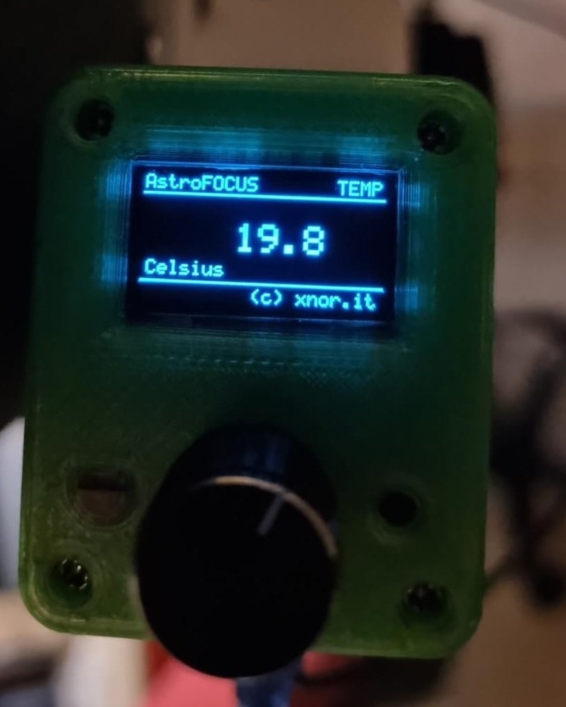
void screenTemp(void) {
char buffer[20];
ClearBitmap();
/* 123456789012345678901*/
WriteString(1, 0, 0, "AstroFOCUS TEMP");
HLine(0, 9,128);
dtostrf(focuserTemperature,8,1,buffer);
WriteString(2,0,24, buffer);
WriteString(1, 2,44, "Celsius");
WriteString(1, 58,57, "(c) xnor.it");
HLine(0,54,128);
ssd1306_RefreshDisplay();
}
void screenFocuserTarget(void)
{
char temp[30];
char buffer[20];
ClearBitmap();
/* 123456789012345678901 */
WriteString(1, 0, 0, "AstroFOCUS TARGET");
HLine(0, 9,128);
sprintf((char*)temp, "%8ld",focuserMoveToTarget);
WriteString(2, 0,22, temp);
dtostrf(focuserMicronsPerStep,6,2,buffer);
sprintf((char*)temp, "%s micron x step",buffer);
WriteString(1, 0,44, temp);
WriteString(1, 58,57, "(c) xnor.it");
HLine(0,54,128);
ssd1306_RefreshDisplay();
}
void screenFocuserMoving(void)
{
char temp[30];
char buffer[20];
ClearBitmap();
/* 123456789012345678901 */
WriteString(1, 0, 0, "AstroFOCUS MOVING");
HLine(0, 9,128);
sprintf((char*)temp, "%8ld",focuserCurrentPosition);
WriteString(2, 0,22, temp);
dtostrf(focuserMicronsPerStep,6,2,buffer);
sprintf((char*)temp, "%s micron x step",buffer);
WriteString(1, 0,44, temp);
WriteString(1, 58,57, "(c) xnor.it");
HLine(0,54,128);
ssd1306_RefreshDisplay();
}
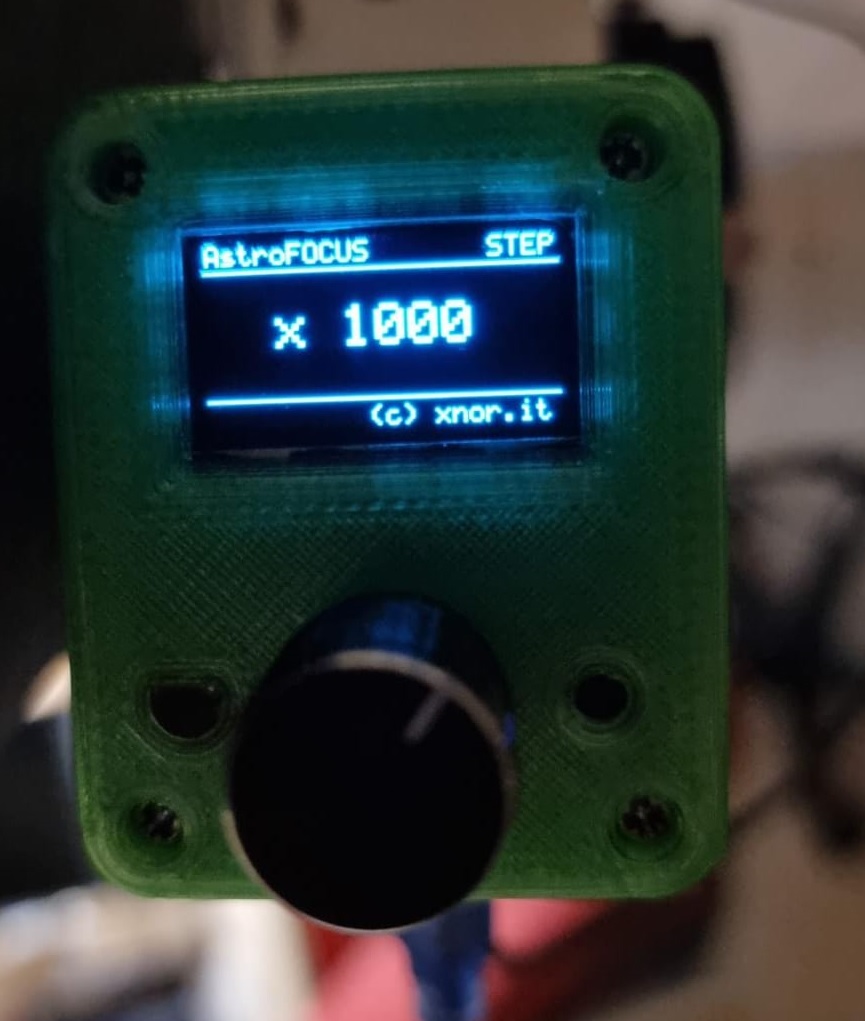
void screenFocuserMultiplier(void)
{
char temp[30];
ClearBitmap();
/* 123456789012345678901 */
WriteString(1, 0, 0, "AstroFOCUS STEP");
HLine(0, 9,128);
sprintf((char*)temp, " x %d",stepMultiplierArray[stepMultiplier]);
WriteString(2, 0,22, temp);
WriteString(1, 58,57, "(c) xnor.it");
HLine(0,54,128);
ssd1306_RefreshDisplay();
}
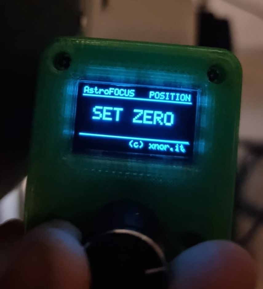
void screenFocuserZero(void)
{
ClearBitmap();
/* 123456789012345678901 */
WriteString(1, 0, 0, "AstroFOCUS POSITION");
HLine(0, 9,128);
WriteString(2, 0,22, " SET ZERO");
WriteString(1, 58,57, "(c) xnor.it");
HLine(0,54,128);
ssd1306_RefreshDisplay();
}
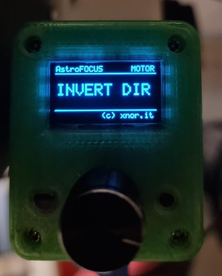
void screenFocuserMotor(void)
{
ClearBitmap();
/* 123456789012345678901 */
WriteString(1, 0, 0, "AstroFOCUS MOTOR");
HLine(0, 9,128);
WriteString(2, 0,22, "INVERT DIR");
WriteString(1, 58,57, "(c) xnor.it");
HLine(0,54,128);
ssd1306_RefreshDisplay();
}
// Encoder functions
void encoderInit (void) {
pinMode(ENCODER_CLK, INPUT_PULLUP);
pinMode(ENCODER_DATA, INPUT_PULLUP);
pinMode(ENCODER_SW, INPUT_PULLUP);
attachInterrupt(digitalPinToInterrupt(ENCODER_CLK), updateEncoder, CHANGE);
attachInterrupt(digitalPinToInterrupt(ENCODER_DATA), updateEncoder, CHANGE);
encoderValue = 0;
encoderOldValue = 0;
}
void updateEncoder() {
int8_t MSB = digitalRead(ENCODER_CLK); //MSB = most significant bit
int8_t LSB = digitalRead(ENCODER_DATA); //LSB = least significant bit
int8_t encoded = (MSB << 1) | LSB; //converting the 2 pin value to single number
int8_t sum = (lastEncoded << 2) | encoded; //adding it to the previous encoded value
if(sum == 0b1101 || sum == 0b0100 || sum == 0b0010 || sum == 0b1011) encoderValue++;
if(sum == 0b1110 || sum == 0b0111 || sum == 0b0001 || sum == 0b1000) encoderValue--;
lastEncoded = encoded; //store this value for next time
}
void processEncoder(void)
{
static bool stepMultiplierMode = false;
static int8_t OldstepMultiplier = 0;
if(!digitalRead(ENCODER_SW) && focuserIsMoving == false)
{
if (stepMultiplierMode)
{
stepMultiplierMode = false;
if (stepMultiplier == 5){
stepMultiplier = OldstepMultiplier;
focuserCurrentPosition = 0;
focuserMoveToTarget = focuserCurrentPosition;
EEPROM.put(EEPROM_CURRENT_POSITION,focuserCurrentPosition); // Store focuser Current Position
delay (100);
}
if (stepMultiplier == 6){
stepMultiplier = OldstepMultiplier;
focuserMotorDirection = !focuserMotorDirection;
EEPROM.put(EEPROM_MOTOR_DIRECTION,focuserMotorDirection); // Store Focuser Motor direction
delay (100);
}
screen = 0;
oneSecondTimer = 0;
screenFocuser();
}
else
{
stepMultiplierMode = true;
OldstepMultiplier = stepMultiplier;
screen = 0;
oneSecondTimer = 0;
screenFocuserMultiplier();
}
delay (500);
}
encoderRealValue = encoderValue/2;
if(encoderOldValue != encoderRealValue && focuserIsMoving == false)
{
if (stepMultiplierMode)
{
if (encoderOldValue < encoderRealValue ) stepMultiplier++;
else stepMultiplier--;
if(stepMultiplier < 0) stepMultiplier = 0;
if(stepMultiplier > 6) stepMultiplier = 6;
encoderOldValue = encoderRealValue;
screen = 0;
oneSecondTimer = 0;
switch(stepMultiplier){
case 5:
screenFocuserZero();
break;
case 6:
screenFocuserMotor();
break;
default:
screenFocuserMultiplier();
break;
}
}
else
{
if (encoderOldValue < encoderRealValue ) focuserMoveToTarget += stepMultiplierArray[stepMultiplier];
else focuserMoveToTarget -= stepMultiplierArray[stepMultiplier];
encoderOldValue = encoderRealValue;
screen = 0;
oneSecondTimer = 0;
screenFocuserTarget();
}
}
else
{
if (focuserIsMoving)
{
screen = 3;
screenTime = 1;
}
else screenTime = 3;
if(oneSecondTimer > screenTime) // Attendi screenTime in secondi prima di cambiare schermata
{
oneSecondTimer = 0; // Resetta il timer
stepMultiplierMode = false;
if(screen == 0) screenFocuser();
if(screen == 2) screenTemp();
if(screen == 3) screenFocuserMoving();
if(screen == 4) screenFocuserMultiplier();
screen++; // Passa alla schermata successiva
if(screen > 2) screen = 0;
}
}
}
void processSensors(void){
if (oneSecondSensorTimer >= 60 && focuserIsMoving == false) { // Leggi la temperatura ogni 60 secondi
//flatBatteryVolt = (analogRead(BATTERY_VOLT) * 0.0048) * 5.737; // Lettura tensione batterie
focuserTemperature = ds1820_read();
oneSecondSensorTimer = 0;
}
}
/*** MAIN *********************************************************************/
void setup()
{
Serial.begin(9600);
Serial.setTimeout(10000);
Wire.begin(); // Initiate the Wire library
Wire.setClock(400000L); // i2c clock
#ifdef ENCODER_DISPLAY
ssd1306_Init();
ssd1306_FlipDisplay(false);
ClearBitmap();
LoadBitmap(BitmapWelcome); // Welcome logo
ssd1306_RefreshDisplay();
#endif
focuserDriverOff = true; // disable driver output
focuserMotorDirection = true;
focuserIsMoving = false;
focuserSaveEEprom = false;
stepMultiplier = 0;
if(restoreEEpromConfig() == false)
formatEEpromConfig(); // Restore EEprom config
initStepMotor();
#ifdef ENCODER_DISPLAY
encoderInit();
#endif
focuserTemperature = ds1820_read();
oneSecondSensorTimer = 0;
lastMillisecond = millis();
screen = 0;
}
void loop() {
processSerialCommand();
processTiming();
#ifdef ENCODER_DISPLAY
processEncoder();
processSerialCommand();
#endif
#ifdef TEMPERATURE_SENSOR
processSensors();
processSerialCommand();
#endif
}
Now you can compile and upload the firmware on the Arduino NANO board.
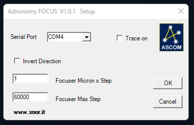
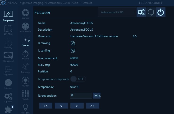
ASCOM Driver
We wrote the Astronomy FOCUS ASCOM driver with Microsoft Visual Studio. We tested it only on windows 10 and 11 64 bit version with NINA program and ASCOM 6.6 platform.
Please let us know if you find any bug related to this driver.
Here you can download the 64 bit version of Astronomy FOCUS ASCOM driver for Windows 10 and Windows 11.
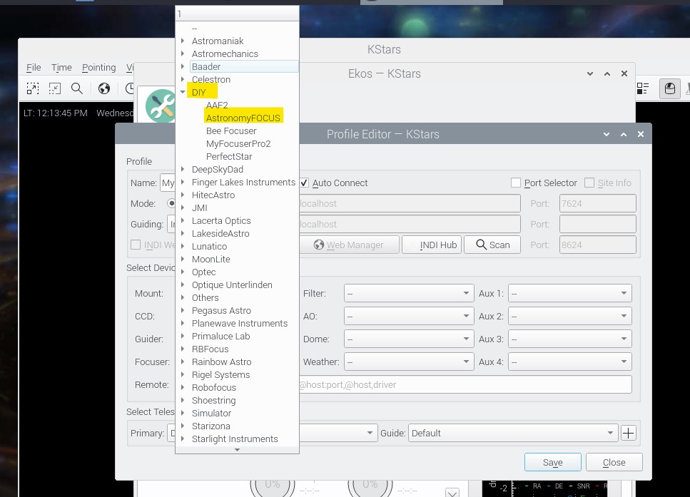
INDI Driver
We wrote the Astronomy FOCUS INDI driver and we tested it on Astroberry and Ubuntu.
Please let us know if you find any bug related to this driver.
Below is reported the procedure to install this driver on Astroberry:
Download and unzip Astronomy FOCUS-INDI-Driver.zip in Astroberry home/astroberry/ directory.
Open terminal and perform the following commands:
cd home/astroberry/xnor/driver/indi-astrofocus
sudo apt install cmake
sudo apt install libcfitsio-dev
cmake -DCMAKE_INSTALL_PREFIX=/usr .
make
sudo make install
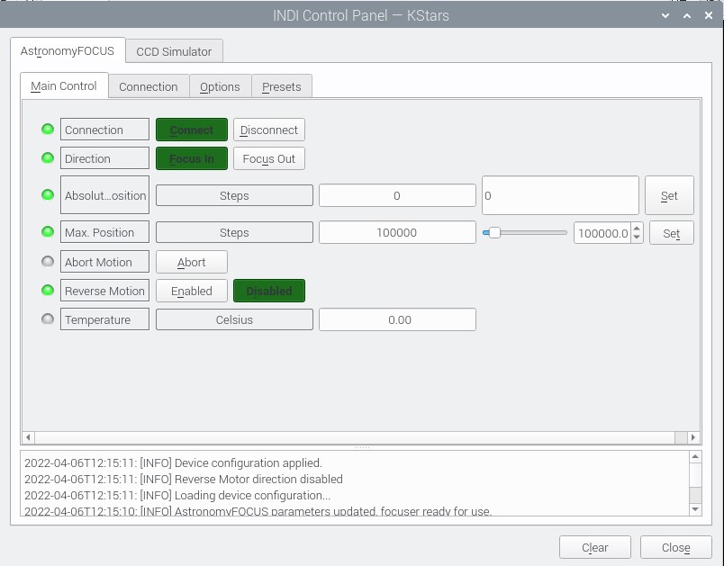
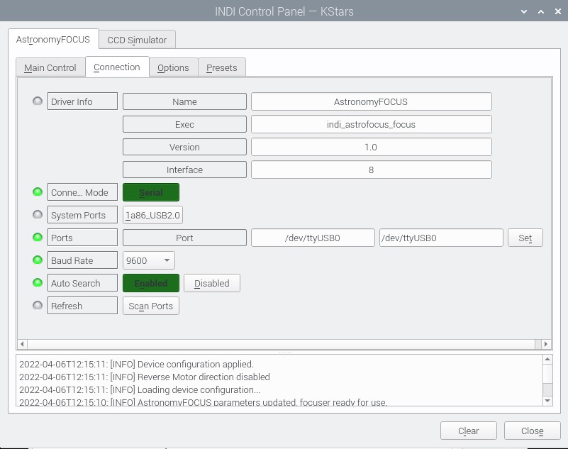
Now you can test the driver on KStars.
Here some screenshot from KStars
Arduino NANO reset behaviour
The Arduino NANO board use the serial DTR signal to reset the microcontroller. The DTR reset is used by Arduino IDE to activate the bootloader installed on the microcontroller and perform the firmware download. We found a strange behaviour on some compatible Arduino NANO boards. Sometime the ASCOM driver fail to connect the Astronomy FOCUS COM port. During the troubleshooting we verified that the DTR perform the microcontroller reset when the ASCOM driver open the serial port. This reset cause an Arduino microcontroller hang (I still don’t understand why…). In order to fix this problem we disactivate the DTR reset by removing the following capacitor component from the Arduino NANO board.
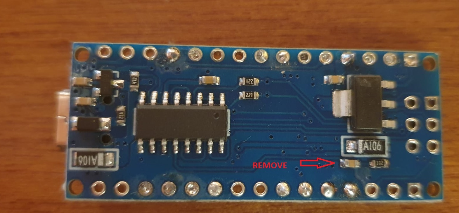
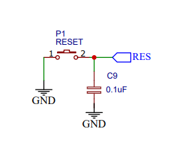
Removing this capacitor we disable the DTR reset and the Arduino IDE will fail the firmware download. In order to download the firmware on the modified board, we need to press the reset button one or two second after the IDE start the download. For this reason we added the following external reset button to the project.
How to build Astronomy Focus
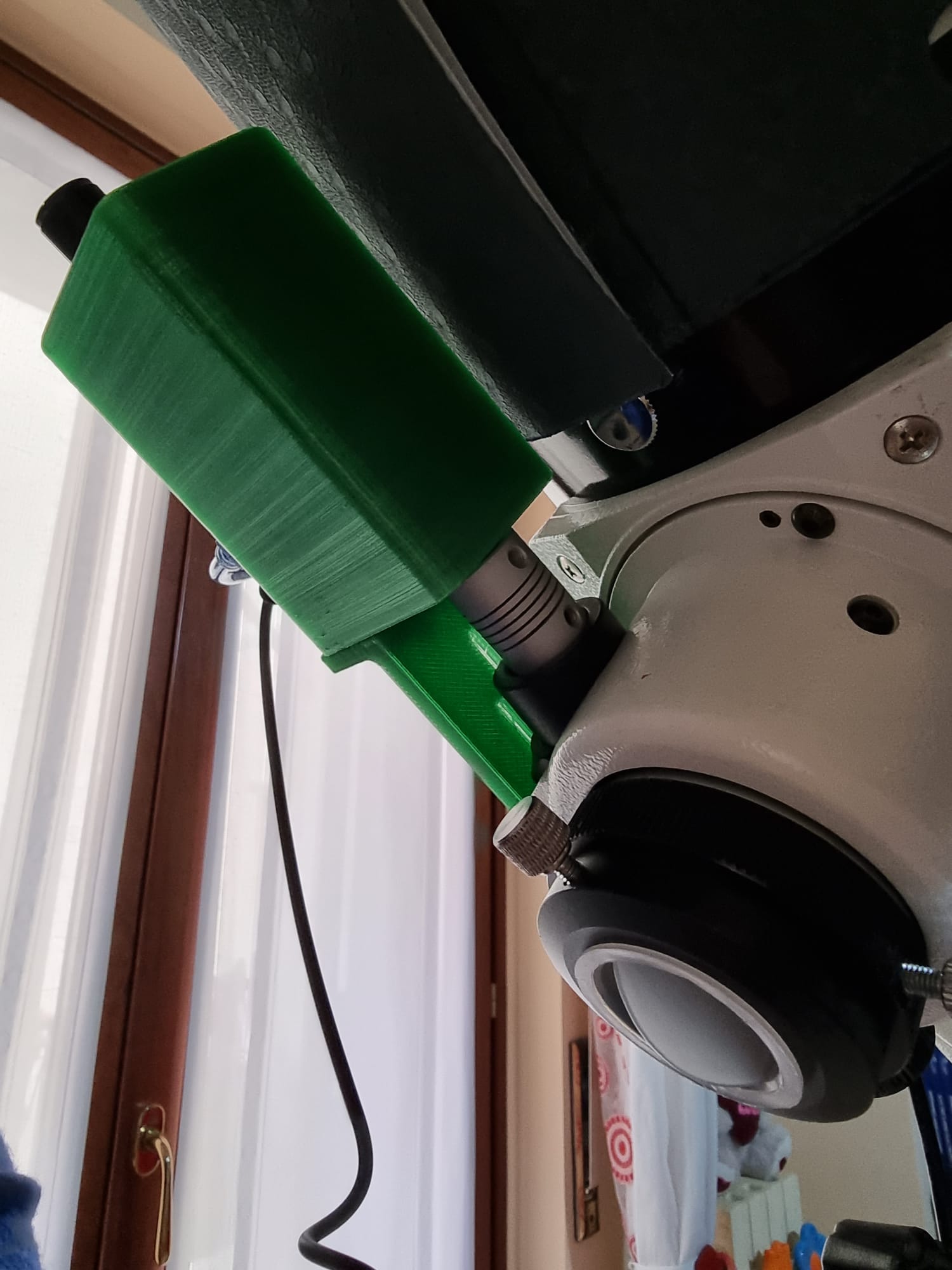
The stepper motor should be connected to the focuser using self-made brackets and adapters.
You can choose transmission via pulleys and belt.
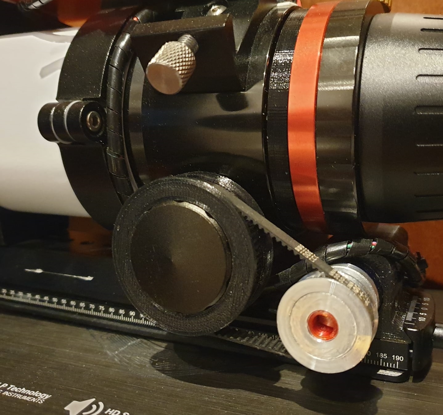
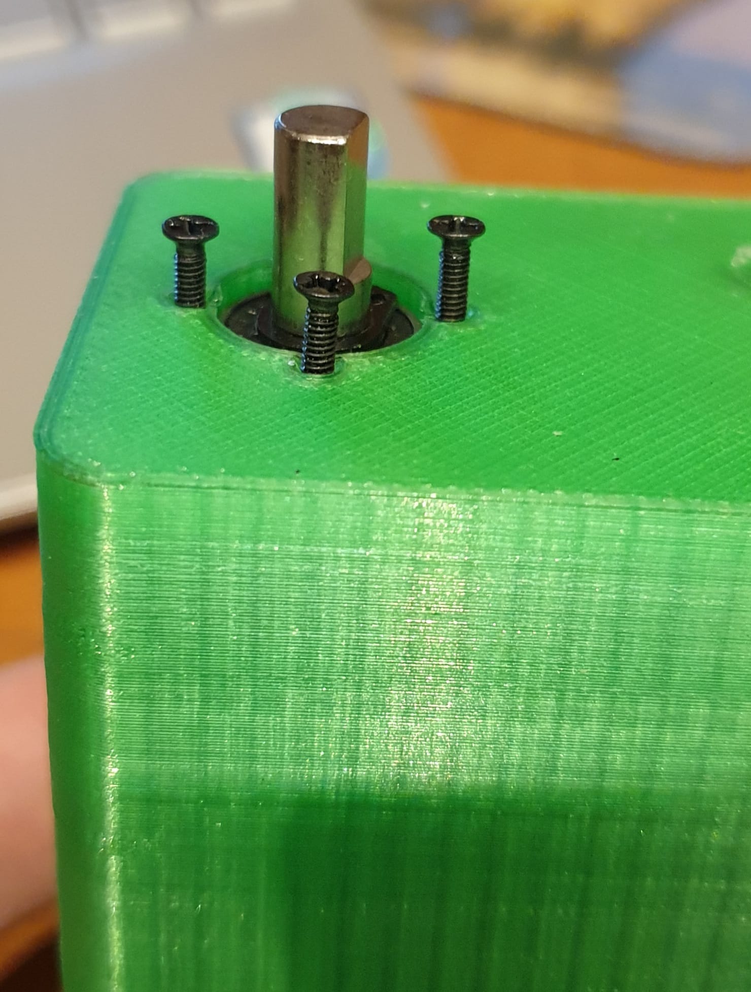
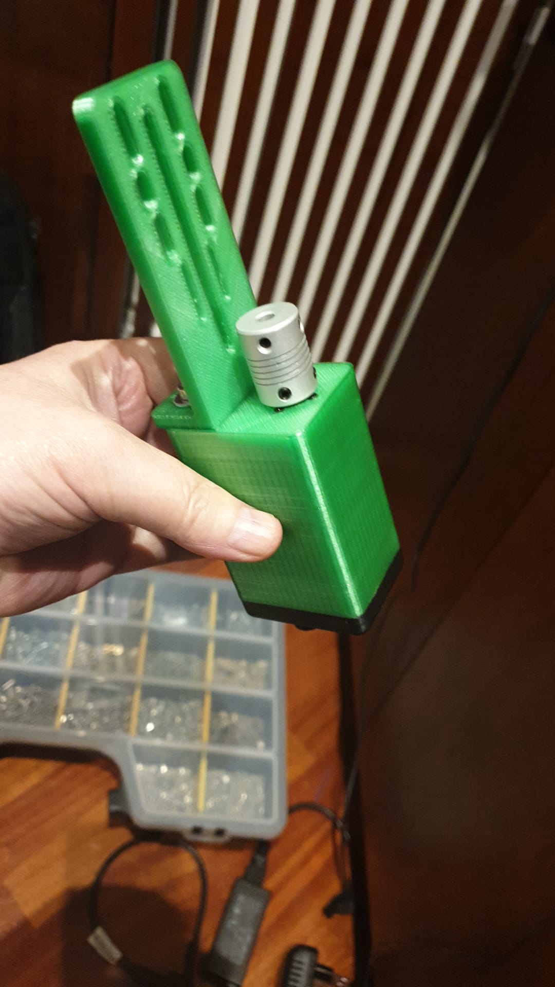
Or you can directly connect the non-geared axis of the focuser to the stepper motor.
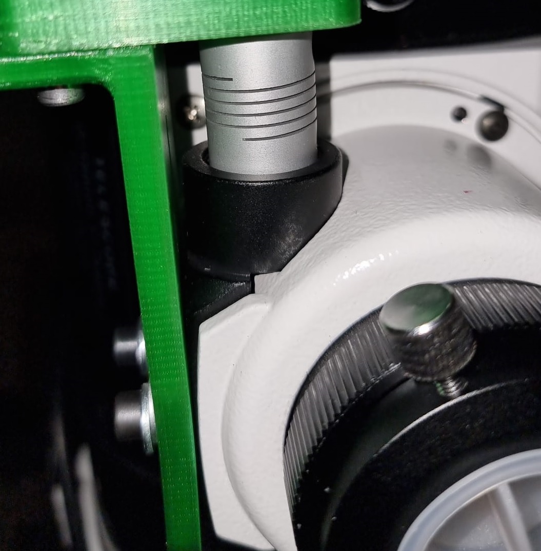
In our project we choose the second option as some commercial focusers do
The Astronomy FOCUS case has been designed with Autodesk Fusion 360
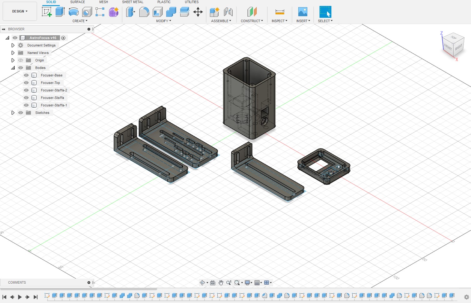
Here you can download the Fusion 360 project:
The Astronomy FOCUS case and brackets are 3D printed with PETG filament.
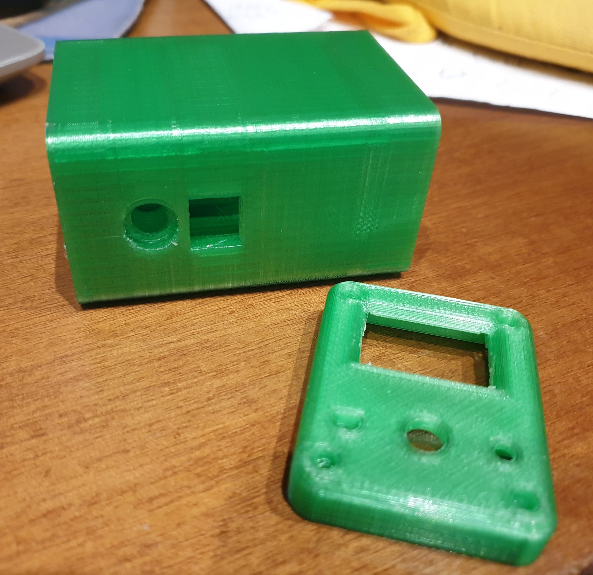
Here you can download the STL files:
Assembling
Assembling the Astronomy FOCUS is not that difficult, you just have to pay attention to the wiring of the electronic part. Since we have not developed a PCB for this model of case, the circuit must be soldered on a bread-board and all connections must be done by hand. The success of the wiring lies in the skill of the person who carries it out. We have used the wiring diagram type 1 and the wiring diagram type 2 only for 12V power supply.
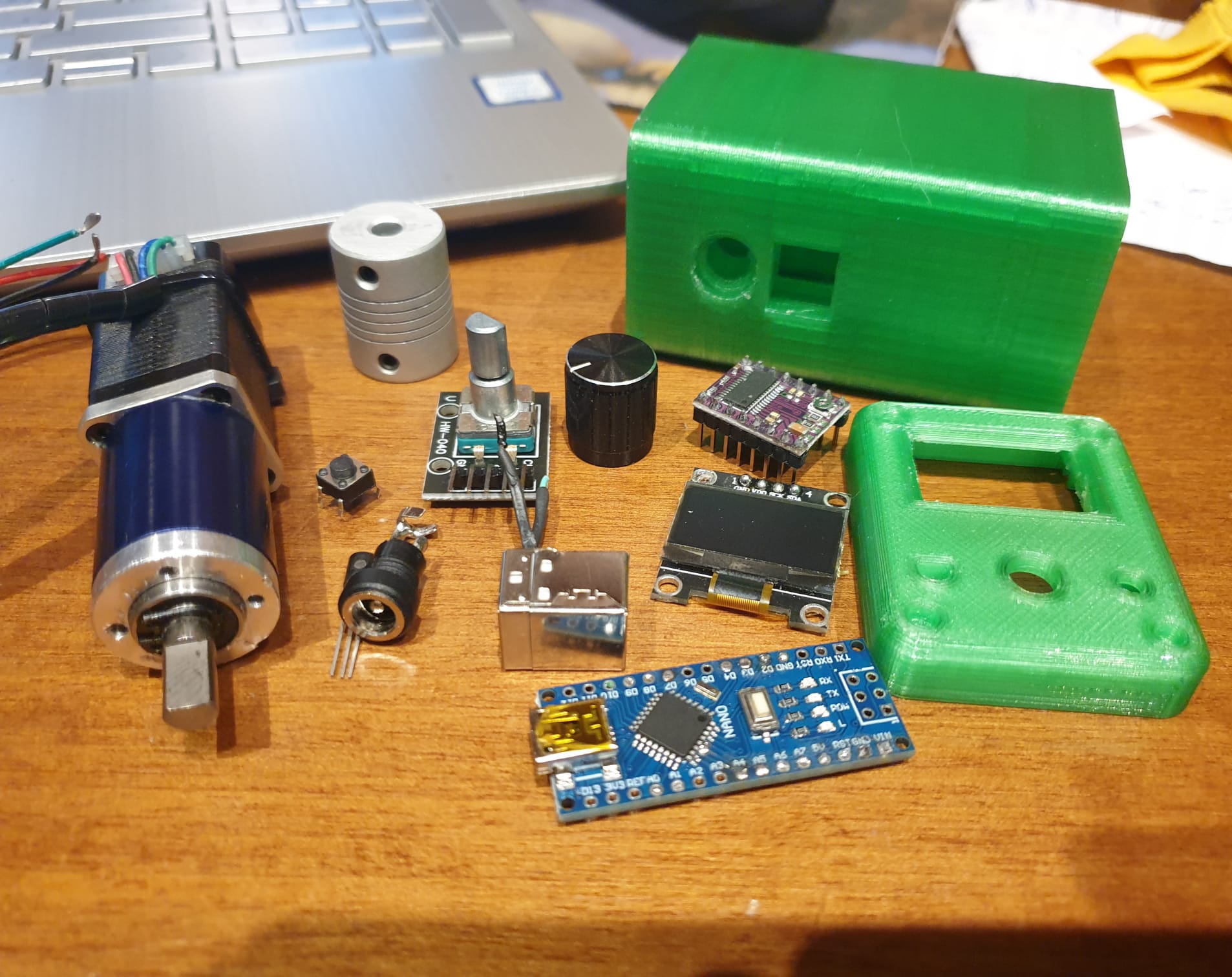
Below I put some pictures of the assembly process:
1 – Have all the components and accessories for assembly available.
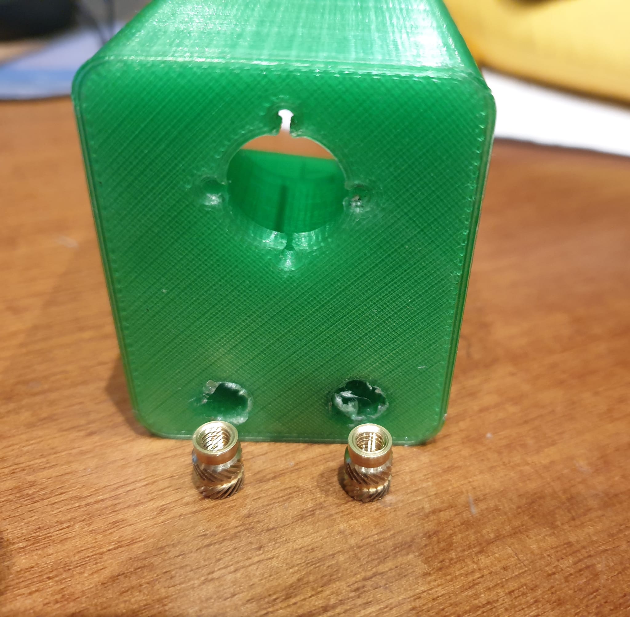
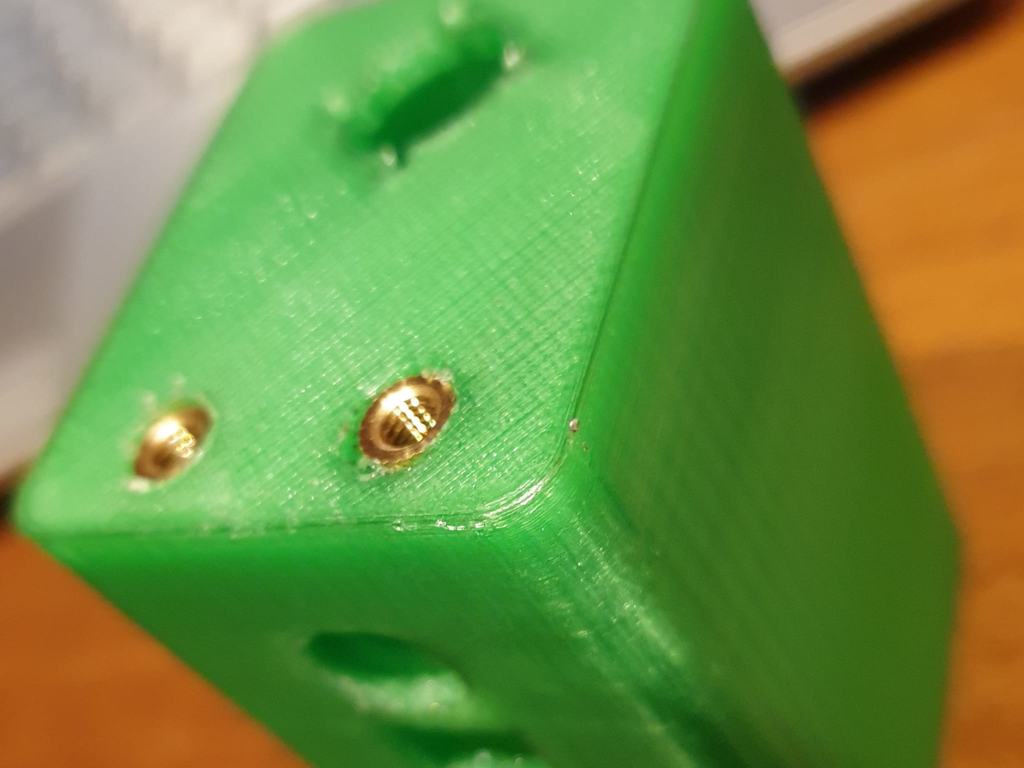
2 – Insert the M4 female threaded bushings into the plastic. To do this I used the soldering iron
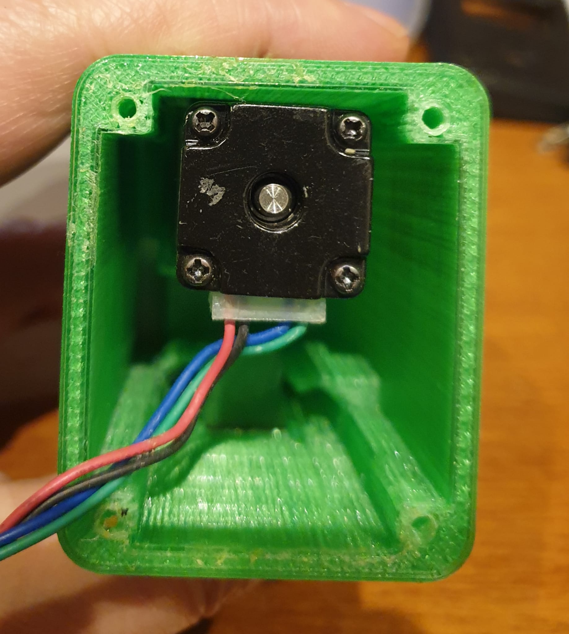
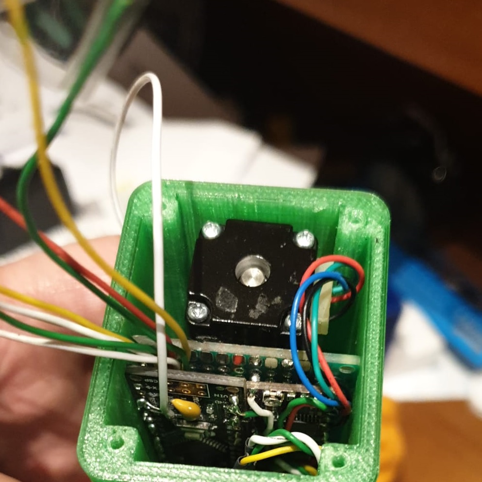
3 – Insert the motor in its housing and screw it with four M2 6mm screws
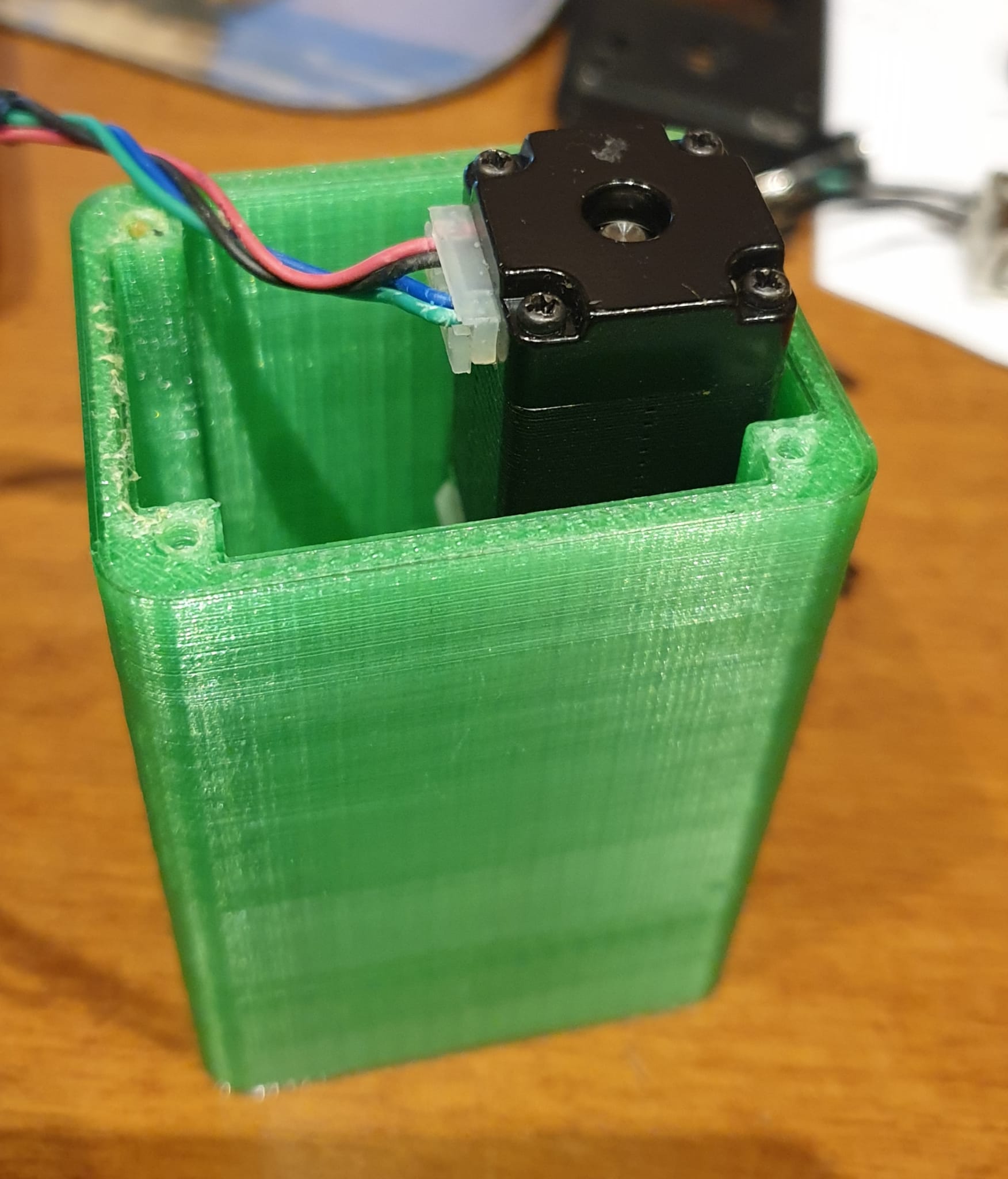
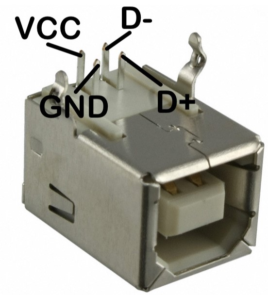
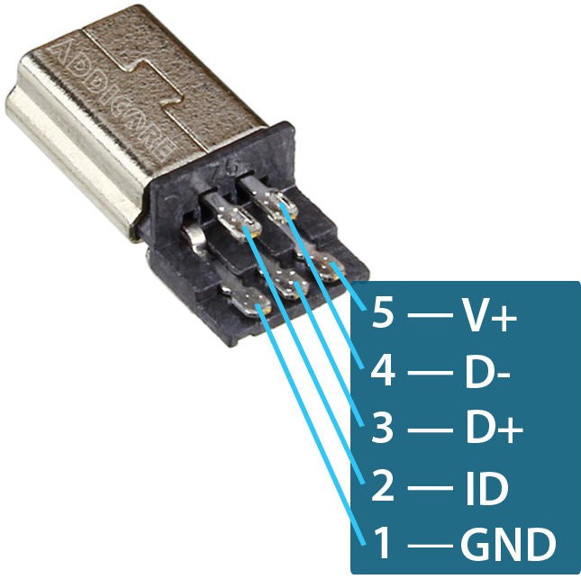
4 – Get a USB-B connector and a male MINI USB connector like those in the following figures. Connect the GND, D +, D- pins of the two connectors together with 10 cm of insulated electric wire.
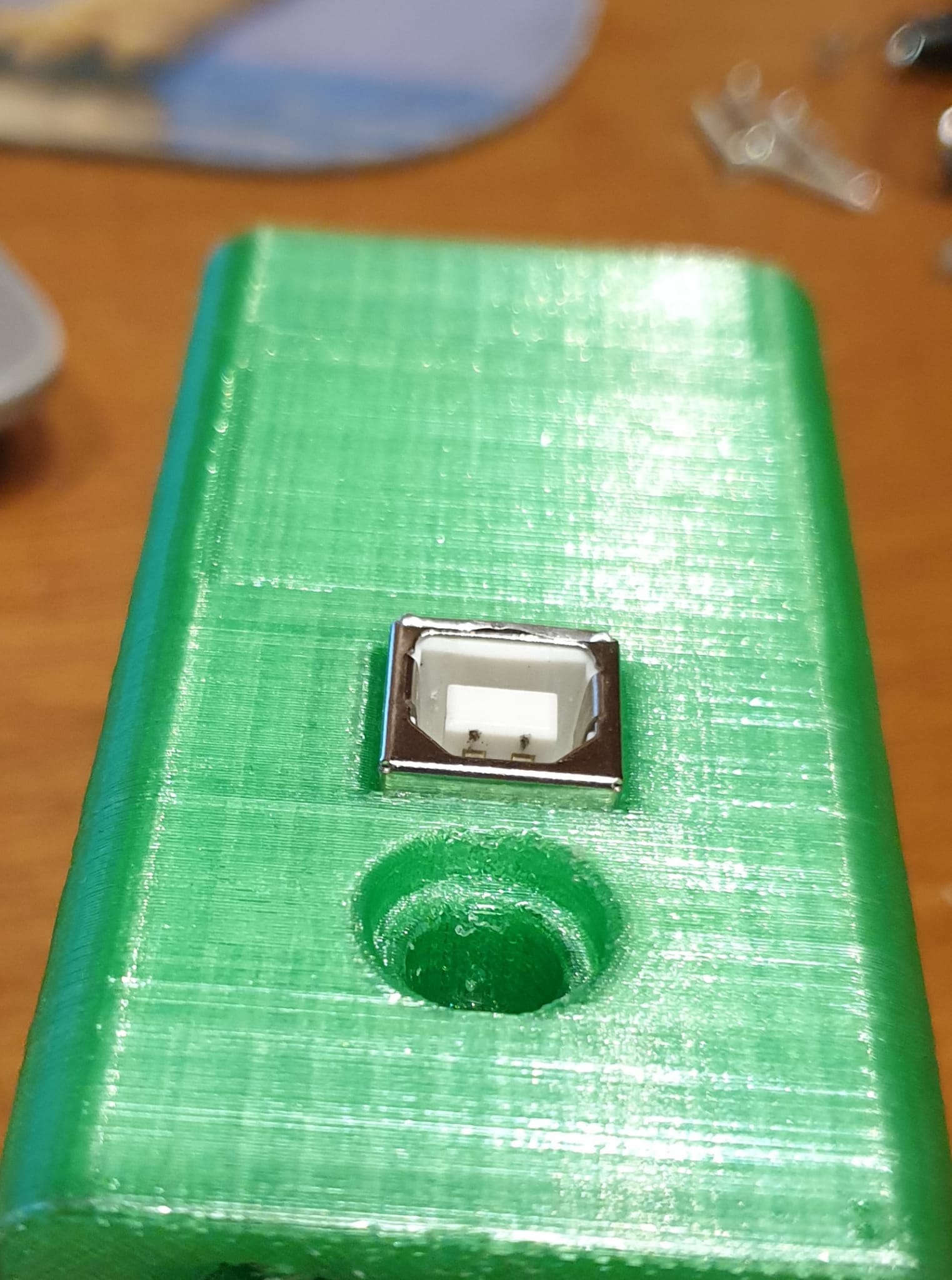
5 – Place the USB-B connector in the special housing by inserting it from the inside of the container and letting it protrude outside by 3 mm
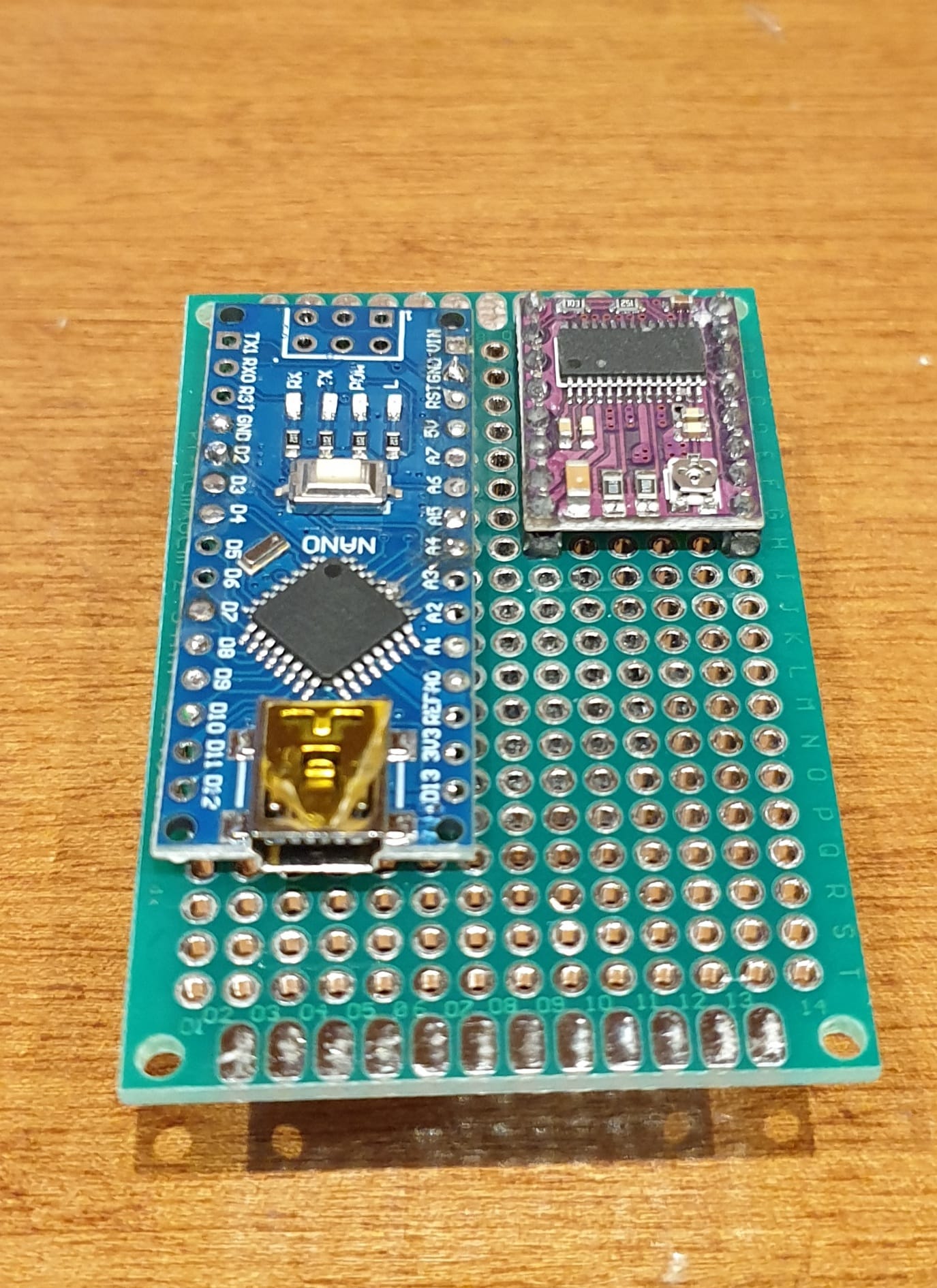
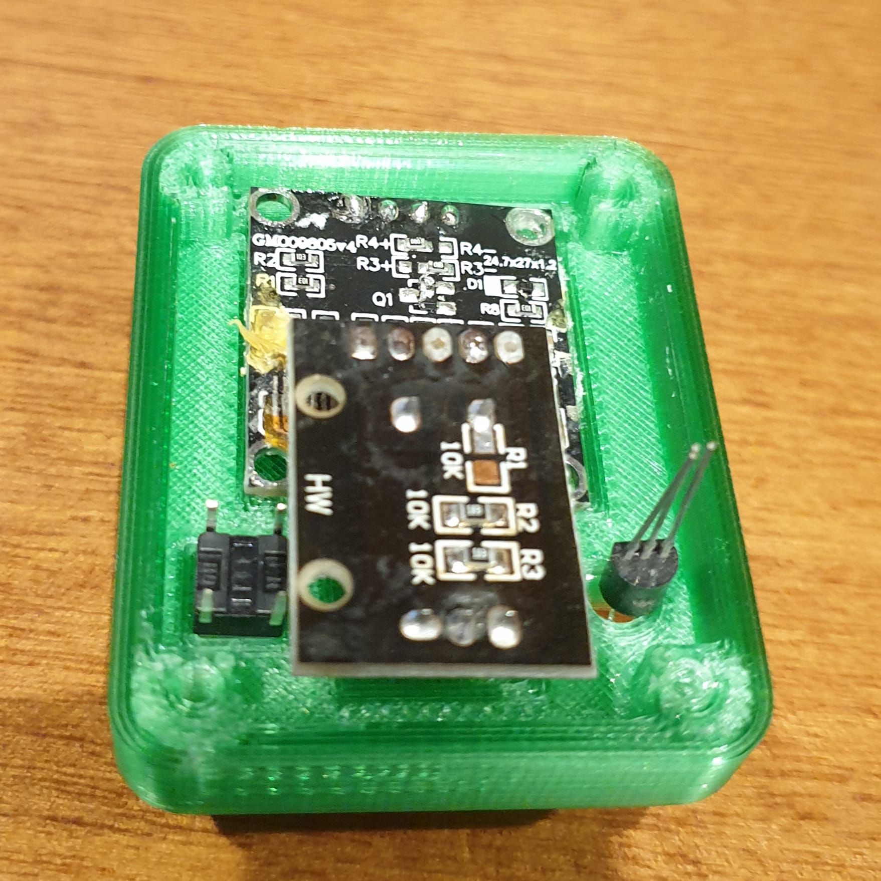
6 – Wire the Arduino Nano board and the DRV8825 driver on a 60×35 mm bread-board. Connect the MINI USB connector to Arduino NANO board and place the wired card into the housing letting the wires for the display, encoder, sensor, reset and power come out from the top.
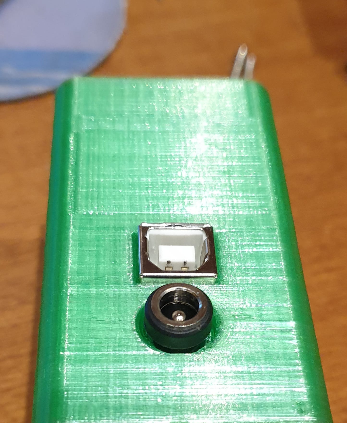
7 – Wire the female 12V power connector, insert it in its housing and connect it to the electronic board
8 – Place in the top cover the display, reset button, encoder and temperature sensor. wire as per wiring diagram all these modules each other and to the processor board included +5V and GND
9 – Test the functioning of the Astronomy FOCUS. Screw the top cover with 2.5x18mm parker screws and insert the encoder knob.
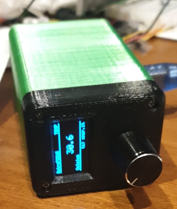
10- Perform the final test
Conclusion
We have reached the end of the post and we want to thank you for your patience. This project took us a long time, but it gave us a lot of satisfaction. We can consider it a starting point and it can also be improved with your support. Hello everyone and see you soon for the next project
Vittorio and Giuliano
IMPORTANT NOTICE
If you’ve any doubt, or you don’t feel confident or comfortable in building this project on you own, search for help from some more experienced friend or from an adult if you’re a minor. You shouldn’t anyway be able to create problems or to put yourself at risk, since the circuit operates at low voltages. It’s anyway easy, in case of mistake, to fry some component and make it unusable or even damage your telescope or accessories. Please check and recheck before powering. Try not to mess up with wires and connections when the circuit is powered. Pay attention to brecelets, tools, watches, or anything metallic which can make short circuits falling on the breadboard. Never leave the circuit unattended when powered. Short circuits or improper cabling may damage the USB host or the USB power adapter.
DISCLAIMER
Even if the circuit operates at low voltage, being this is an hobbystic project, we cannot take any responsibility and you build the circuit AT YOUR OWN RISK, not being hereby implied any WARRANTY for any damage, injury or consequence, nor guaranteeing fitting for any particular purpose.
Gran lavoro ragazzi, non so se riuscirò a portarlo a termine ma sembra che non manchi nulla per essere perfetto. Io ci provo nel dubbio posso sperare assistenza? Grazie e bravi
Ciao Guido,
Certo se hai dubbi puoi contattarci sulla mail indicata nel sito
Vittorio
Complimenti per la chiarezza e la disponibilità, appena posso ci provo, grazie
Grazie Federico
Complimenti per il progetto e grazie per la condivisione.
Posso chiedere se il fuocheggiatore può essere controllato anche tramite sistema astroberry su raspberry?
Grazie
Ciao Fabio.
Al momento non abbiamo ancora scritto i driver INDI quindi ad oggi e’ solo supportato su windows.
Ci stiamo documentando per potere scrivere anche i driver INDI però al momento non so dare una stima del tempo che ci vorrà.
Grazie
Vittorio
Ciao Fabio,
Ho aggiunto i driver INDI per controllare questo focheggiatore anche da astroberry su raspberry.
Nella pagina trovi la procedura per installare i driver INDI
Vittorio
Grazie!!!
Cari Vittorio e Fabio, sto seguendo il vostro schema 1 con display e encoder, ma non comprendo il particolare jp3.
Il sensore di temperatura ha tre terminali ma qui ne sono indicati cinque.
Ciao Guido Maria,
Ciao,
Per collegare il sensore devi usare il connettore JP3
lato sensore vdd lo colleghi al connettore pin 5V
lato sensore il GND lo colleghi al connettore GND
lato sensore il DQ lo colleghi al connettore TMP.
Gli altri pin del connettore A1 e A2 erano previsti per sviluppi futuri.
se non vuoi mettere un connettore basta che colleghi i fili alla scheda arduino ma devi sempre mettere la resistenza di pullup R1 tra TMP e +5V come da schema
Commento di prova
commento di test