
How the circuit works
And now we’re ready to explain you how the emulator circuit works !
The project is not that complex, and maybe you want to try on your own. Before talking about materials and connections let’s talk about the main components and electric schematics.
PLEASE if you’re not expert or confident with electronics, or if you’re a minor, seek for help from an experienced adult. This is not a dangerous project but something can always go wrong. Please read also che disclaimer at the end of the page.
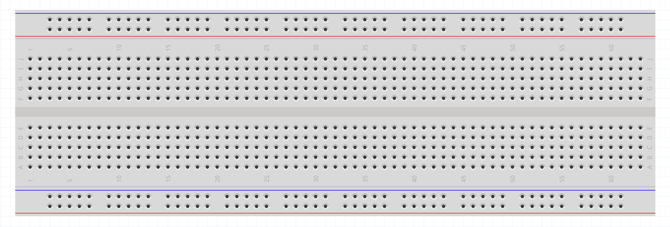
To start playing you need to get a “breadboard”. A breadboard is a rapid and cheap prototyping board where there are holes for connections arranged in an useful way: all the holes near the blue line are connected togheter and used for “negative”, all the holes near the red line are connected togheter and used for “positive”, all other holes are vertically connected in group of five, and used to connect components.
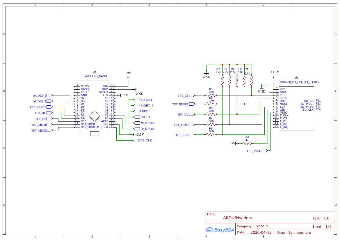
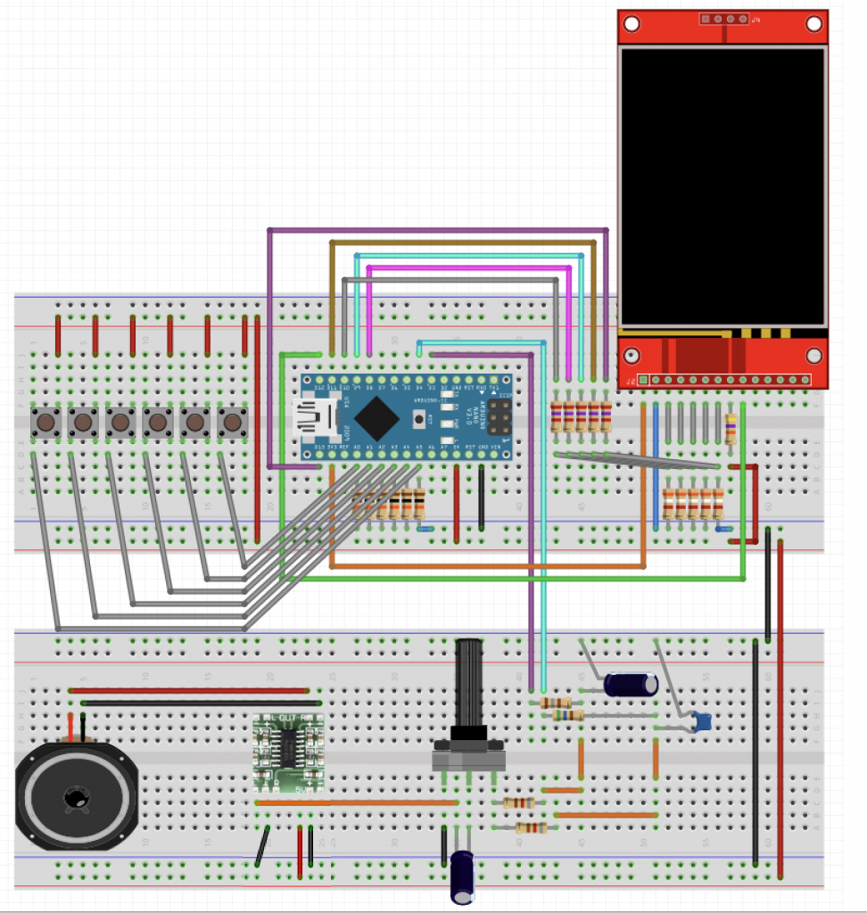
The project is based on the Arduino Nano V3 microcontroller and a 2.8 inches LCD display, the ILI9341 from Ilitek. In the next diagram you can see the Arduino Nano on the left and the Display on the right. The Arduino may be powered by an USB cable (the same cable you use to program the Arduino) or by a 9 volt DC source (battery or DC PSU), useful to play far from a PC or without an USB power adapter.
Arduino generates also 5 volts and 3,3 volts DC, useful to power the display. Moreover we’ve to connect data lines between Arduino and the display to make them talk to each other.
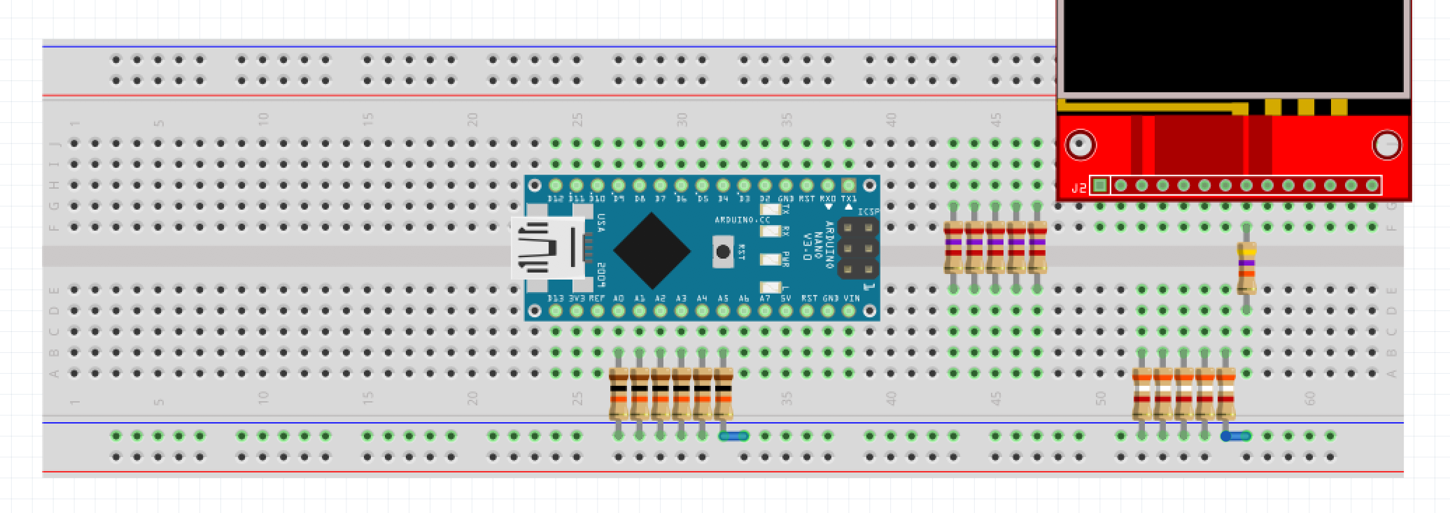
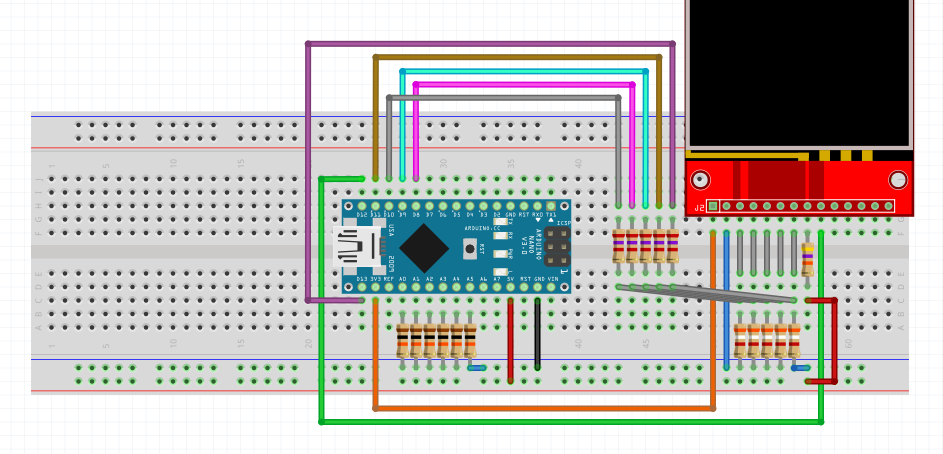
To start making the connections depicted above you should place che Arduino and the Display on the breadbord in a comfortable disposition. In the next picture you can see the Arduino board (USB connector on the left), the Display (pin 1 on the left), and four groups of resistors:
- Group 1 (on the left). Those are six 10 kOhm 1/4 watt resistors (R12, R13, R14, R15, R16, R17 in the schematics) dedicated to controls (schematics later in this page). Please note that those resistors connect Arduino’s pins A0, A1, A2, A3, A4, A5 to ground (negative), and note that the last resistor on the right should be connected to the adjacent ground “hole”. We will discuss later about this part of the circuit.
- Group 2 (center). Those are five 3,9 kOhm 1/4 watt resistors (R1, R2, R3, R4, R5 in the schematics) that connect one leg of the five voltage dividers to Arduino pins D13/SCK, D11 MOSI, D10, D9, D8 to (from the Display pins CLK, MOSI, CS, DC and RESET).
- Group 3 (right). Those are five 2,7 kOhm 1/4 watt resistors (R7, R8, R9, R10, R11 in the schematics) that connect the other leg of the five voltage dividers from Diplay pins (3 CS, 4 RESET, 5 DC, 6 MOSI, 7 SCK) to ground. Please note that the last resistor on the right should be connected to the adjacent ground “hole”.
- Group 4 (the last resistor on the right) is a single 47 Ohm 1/4 watt resistor (R6) which connects the display retroillumination to the 5V source coming from Arduino.
Before connecting all those resistors we’ve to take care of powering. From left to right you should:
- Connect (orange wire) Arduino pin 3v3 (3,3 volts source) directly to display pin 1 (VCC)
- Connect (red wire) Arduino pin 5V (5 volts source) to the bottom breadboard bar (red line pins)
- Connect (black wire) Arduino pin GND (ground) to the bottom pins of the breadboard (blue line pins)
- Connect (blue wire) display pin 2 (GND) to the bottom bar of the breadboard (blue line)
- Connect (red wire) the bottom pin of the 47 Ohm resistor on the far right (upper pin is connected to display pin 8 (LED)), to the bottom bar of the breadboard (red line) to get 5V source.
Once powering lines are complete you can prepare the voltage dividers. You need to arrange 5 wires (grey wires) from the bottom pins of the resistor Group 2 to the upper pins of resistor Group 3, and 5 more wires from (grey vertical wires) from the Display pins 3,4,5,6,7 to the upper pins of Group 3 resistors.
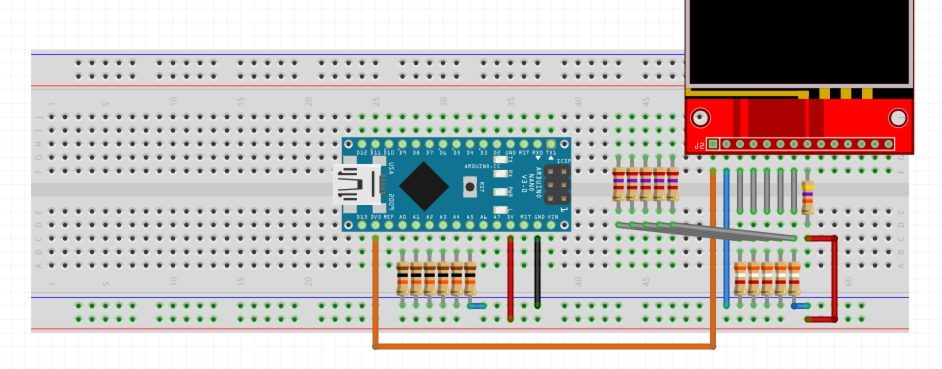
The voltage dividers are needed since Arduino works with 5V signal level, while the display works with 3,3 volts signal level. If we connect Arduino outputs straight to the Display the display would broke. The voltage divider brings, through the resistors, part of the voltage to groud, thus lowering the 5 volts from Arduino to less than 3,3 volts, thus being compatible with the display inputs.
Now we just have to connect a few more wires: Group 2 resistors to Arduino, and a signal that goes straight from Display pin 9 (MISO) to Arduino pin D12 (MISO). Since this last signal originates at 3,3 volts from the Display it can directly be fed to the Arduino without a voltage divider.
The five connections you’ve to make for resistors Group 2 are:
- (grey wire) – Resistor 1 (R1) from Display pin 3 (CS) to Arduino pin D10
- (purple wire) – Resistor 2 (R2) from Display pin 4 (RESET) to Arduino pin D8
- (cyan wire) – Resistor 3 (R3) from Display pin 5 (D/C) to Arduino pin D9
- (brown wire) – Resistor 4 (R4) from Display pin 6 (MOSI) to Arduino pin D11 (MOSI)
- (dark purple wire) – Resistor 5 (R5) from Display pin 7 (SCK) to Arduino pin D13 (SCK)
Last wire is the green one, from Display pin 8 (MISO) straight to Arduino pin D12 (MISO).
What you’ve done (please check every wire step by step) allows you to power up and program the Arduino (and see something on the display). But with a bit more effort you can prepare controls too. In the following schematics you can see three blocks: controls (on the left), 9 volt battery powering (bottom left), audio amplifier (right). Let’s focus on controls.
The resistors you’ve installed (Group 1) “pull” Arduino analog inputs to “Ground” thus making Arduino read a “zero”. In the schematics you can see “switches” or “buttons” that “pull” Arduino analog inputs to “5 volts” thus making Arduino read an “one” when the switch is closed or the button is pressed.
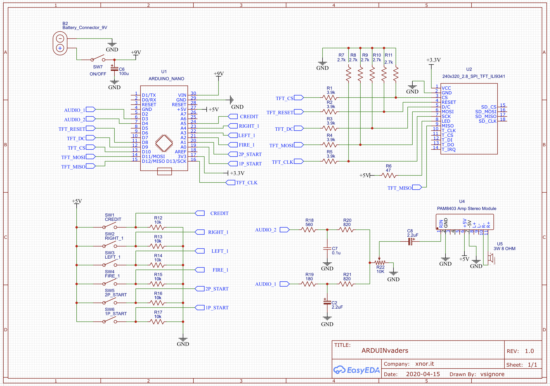
To complete the circuit on the breadboard you just need to bring Arduino analog inputs to a convenient position to host a connector from which you can make a cable to a control board, or a plate where you will install your buttons for Credits (insert COIN), 1 Player start, 2 Players star, Left movement, Right movement, and FIRE !
Please note the leftmost red wire which brings 5 volts from the bottom red bar of the breadboard to the controls connector and notice that pin assignment is:
- A0 – One player start
- A1 – Two players start
- A2 – Fire
- A3 – Move left
- A4 – Move right
- A5 – Credit (coin inserted)
You can use any kind of NO (Normally open) switch or button (open when released, closed when pushed), from microswitches to arrange in a tiny control board to bigger switches like the colorful big ones used in arcades or in the original Space Invaders.
Having done all this you’ve completed everything (except the optional 9V powering and the audio amplifier).
Please note that you can easily collect what is needed to build the project from online portals like Aliexpress, Banggood, Mouser, RS Components, or, if you’re lucky to live near one, from smart electronics local dealers.
The audio amplifier
If you want to hear audio effects you just have to build the latter part, the Audio Amplifier, which we based on the PAM8403 stereo module. Just about ten more components and… you’re done !
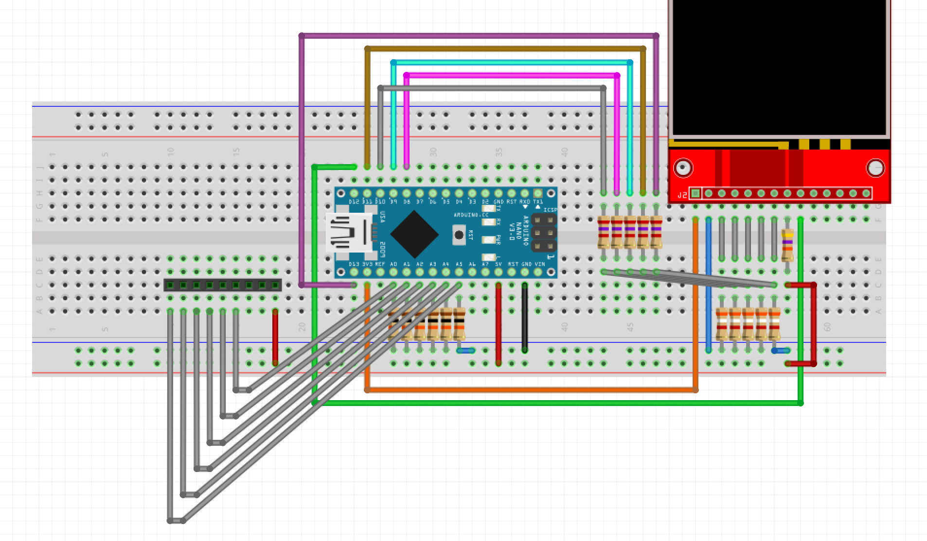
In the next picture you can see a build scheme of the audio part and a possible arrangement of the control switches.
In the scheme above the most important things you should note are:
- The black wire bringing ground (GND) from the first breadboard to the second, and the ground distribution on the second breadboard (four black wires)
- The red wire bringing 5V power from the first breadboard to the second, and the red wire powering the PAM8403 amplifier
- The purple and cyan wires bringing Audio signals from the first breadboard (Arduino pins D3 and D4) to the second breadboard where they’re filtered by two RC couples (Resistor R18/R19 + Capacitor C1/C2) and then mixed by two more resistors (R20/R21) and fed to the volume potentiometer (R22), which has one leg grounded (GND) and the middle leg connected to the positive of capacitor C8 and from there to the RIGHT channel INPUT of the amplifier
- The RIGHT OUTPUT of the amplifier goes straight to the Speaker via the red and black wires.
That’s it !
The BOM (Bill of materials) except the Audio Part is:
- N. 6 button NO (Normally Open) switches (for controls) – Contact closes when pressed
- N. 1 Arduino Nano V3
- N. 1 mini-B USB cable for Arduino
- N. 1 2’8 LCD Display Ilitek 9341 (touch screen not needed)
- N. 1 47 Ohm 1/4 Watt resistor (R6)
- N. 5 3,9 k Ohm 1/4 Watt resistors (R1, R2, R3, R4, R5)
- N. 5 2,7 k Ohm 1/4 Watt resistors (R7, R8, R9, R10. R11)
- N. 6 10 k Ohm 1/4 Watt resistors (R12, R13, R14, R15, R16, R17)
The BOM (Bill of materials) for the sole Audio Part is:
- N. 1 Breadboard (if you want to stay comfortable)
- N. 1 8 Ohm, 3 watt speaker
- N. 1 PAM8403 Amplifier module breakout
- N. 1 2,2 uF capacitor (electrolytic) – (C2)
- N. 1 104 kpF (0,1 uF) capacitor (ceramic or polyester) – (C7)
- N. 1 2,2 uF capacitor (electrolytic) – (C8)
- N. 2 820 Ohm 1/4 Watt resistor (R20, R21)
- N. 1 560 Ohm 1/4 Watt resistors (R18)
- N. 1 180 Ohm 1/4 Watt resistors (R19)
- N. 1 10 kOhm potentiometer or trimmer – Logarithmic (R22)
IMPORTANT NOTICE
If you’ve any doubt, or you don’t feel confident or comfortable in building this project on you own, search for help from some more experienced friend or from an adult if you’re a minor. You shouldn’t anyway be able to create problems or to put yourself at risk, since the circuit operates at low voltages. It’s anyway easy, in case of mistake, to fry some component and make it unusable. Please check and recheck before powering. Try not to mess up with wires and connections when the circuit is powered. Pay attention to brecelets, tools, watches, or anything metallic which can make short circuits falling on the breadboard. Never leave the circuit unattended when powered. Short circuits or improper cabling may damage the USB host or the USB power adapter.
DISCLAIMER
Even if the circuit operates at low voltage, being this is an hobbystic project, we cannot take any responsibility and you build the circuit AT YOUR OWN RISK, not being hereby implied any WARRANTY for any damage, injury or consequence, nor guaranteeing fitting for any particular purpose.