

On September 26th, 2019 we participated to the annual Once Upon a Sprite (OUAS-2019) event in Milan – Copernico Blend Tower – Italy. OUAS events bring togheter retrogaming and retrocomputer enthusiasts. During our speech at the event we presented a project conceived soon after the 2018 OUAS event: an emulator based on cheap and simple hardware to “revive” the original bytecode of the Space Invaders ™ arcade.
Here on this Blog article you can read how we started, how it works, and how to build your own.
The story
It was about 42 years ago (1977) when a young Japanese engineer was asked to design a new coin-op arcade, when state-of-the-art computers were Apple ][, Tandy Radio Shack TRS-80 and Commodore CBM/PET. In Italy it was the year of color on TV with tv shows like Discoring, Portobello, Superclassifica show, Orwozei and The Man from Atlantis. It was also the year of the release of the evergreen masterpiece “Oxygène” by Jean Michel Jarre.
The young engineer Tomohiro Nishikado in just one year conceived for TAITO ™ a spectacular board based on:
- the 8 bit Intel ™ 8080 @ 2 MHz processor
- the Texas Instruments ™ SN76477 sound generation chip
- a screen with 256×224@60Hz resolution, black & white
- 8 KByte ROM – 8 KByte RAM (7 dedicated to video)
- three switches for human player interaction (left, right, fire)
and it soon it became a global success. In Italy it appeared in 1979/80, and there were queues of people that wanted to play. With more thank 360,000 cabinets Space Invaders ™ was one of the first games to introduce the “High score” concept, the “Lives” concept, to be based on a “Bitmap” and to have a sort of continuous soundtrack.
TAITO’s ™ original Space Invaders was black and white, but it is said that the american distributor Midway Games wanted colors. It wasn’t an easy task, since the bitmap had only one bit per pixel, and color was created applying colored plastic transparent films in the case of the game, between the monitor and the glass. Really a good hack !
Emulating using simple and cheap hardware
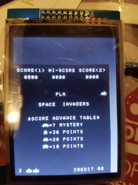
Our goal was to build something that could run the original byte code of Space Invaders but with the lowest number of components, and being as cheap as possibile. We therefore choose:
- Arduino NANO 3.x – ATmega328 @ 16MHz, 32 KByte flash, 2 KByte SRAM
- Ilitek display ILI9341 2’8 (TFT LCD 320×240 256k colors)
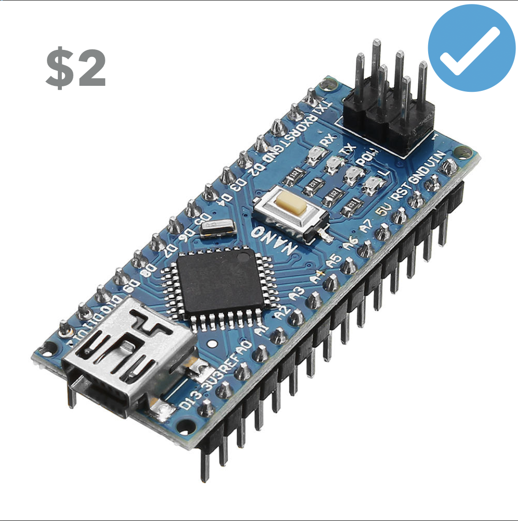
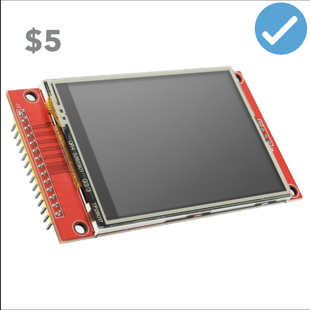
which can be bought (best price on the market) at about $2,00 + $5,00 + some dollars for accessories + shipping from various on-line shops.
First issues – Memory
The first obstacle we had to address was that the memory map of the original game was organized as follows:
- 0x0000-1FFF – 8k ROM on four chips (H*, G, F, E)
- 0x2000-23FF – 1k RAM
- 0x2400-3FFF – 7k video RAM
- 0x4000- RAM mirror
while Arduino Nano has just 2 KByte of RAM. How could we fit 16k in 2k ? We had to find a compromise using Arduinos’ Flash RAM and the display RAM:
- 0x0000-1FFF – 8k(+2k*) ROM will go in Arduino Flash
- 0x2000-23FF – 1k RAM will go in Arduino SRAM
- 0x2400-3FFF – 7k Video RAM will go in LCD/SPI diplay memory
This had anyway some drawbacks. We needed to use some address-based bank switching in read_byte() and write_byte() functions and deal with the problem that the LCD display is a 16 bit per pixel display, and thus wasting SPI r/w and CPU cycles.
First challenges – Audio generation
The original Space Invaders generated audio effects with a huge dedicated audio board based on the Texas Instruments SN76477. Many emulators are based on samples of the original waveforms, but on the Nano we didn’t have memory space for samples, so we opted to emulate the original hardware. Maurizio dealt with that.
More challenges – The hardware shift register
The Intel 8080 chip didn’t have shifting instructions. This is the reason why the game board had some dedicated hardware to do the byte-shifting needed to move the aliens from left to right and vice-versa. The hardware shifting was based on Ports 2/Output, 3/Input, 4/Output. We had to emulate that by software.
Input & output – Input and output registers
Input and output of the game were based on “ports”:
- IN Port 1: Credits, 2 players start, 1 player start, “1”, Player 1 fire, Player 1 left, Player 1 right, “nc”
- IN Port 2: dip3, dip5, Tilt sensor, dip6, Player 2 fire, Player 2 left, Player 2 right, dip 7
- dips 3/5: Ships (3,4,5,6 lives)
- dip 6: Grant an extra ship at 1000 or 1500 points
- dip 7: Coin info displayed on demo screen
- IN Port 3: Shift register input data
- OUT Port 2: Shift register shift amount
- OUT Port 3: Sounds: Ufo, Fire, Player dies, Invader dies, Ext play, AMP, “nc”, “nc”
- OUT Port 4: Shift register shifted data
- OUT Port 5: Sounds: Fleet movement 1..4, Ufo hit, “nc”, “nc”, “nc”
- OUT Port 6: Watchdog (unused in emulator)
“nc” stands for “No Connection”.
But nothing can start without the… credits !
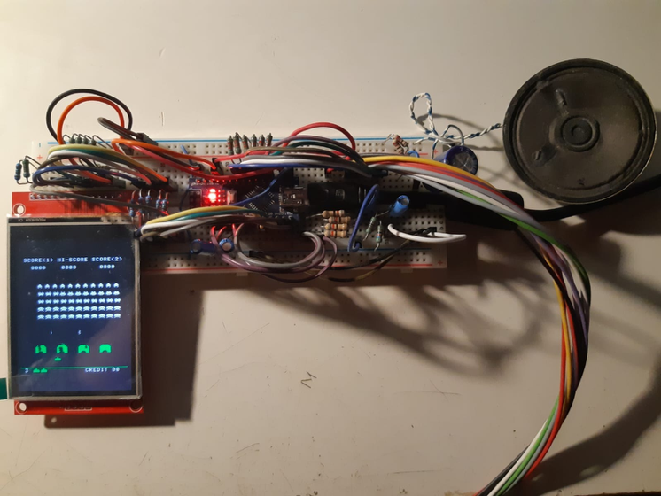
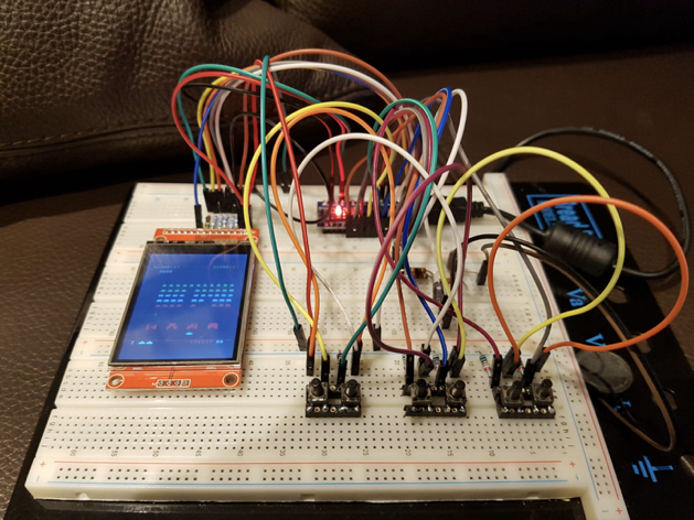
To try to start to do anything we needed an hardware. You can see in the following image one of the first hardware releases…
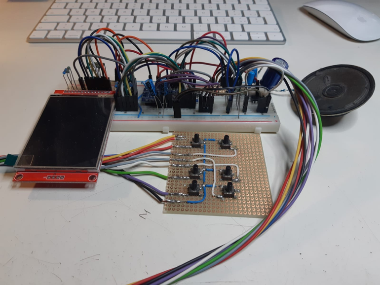
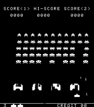
…and who can imagine to do absolutely anything without a proper “credits” screen ?
More challenges – The 8080 processor, the registers
How can a program emulate a processor ? It may sound unusual but even if tricky it is more tedious than complicated. You need to create variables for every register and for every flag. You have to deal with 8 bit and 16 bit registers, which can be used either in 16 bit or 8 bit mode.
We decided to use a C “union” to have a double view (8 and 16 bits) of the same register. Here is an example for the 8 bit registers “B” and “C”, which can be used also as a single 16 bit register “BC”.
typedef union {
    uint16_t BC16;
    struct {
        uint8_t C;
        uint8_t B;
    } BC8;
} reg_BC;
reg_BC BC = { 0x0000 };
More challenges – The 8080 processor, the opcodes
Once register and flags are ready you need to get a good book describing the single opcodes and write a specific function for every opcode for every addressing variant. There are 256 opcodes in the 8080. Here is an example:
void cpu8080_0x00(void) { // NOP :-)
}                         // No operation - It works!

void cpu8080_0x03(void) { // INC BC
 if(++BC.BC8.C == 0)      // Increment bytelow, and,
   ++BC.BC8.B;            // if bytelow is in overflow,
}                         // inrcement bytehigh

void cpu8080_0xfb(void) { // EI
  InterruptFlag = true;   // Enable interrupt flag
}
and, once you’ve created a function for every opcode, you need to write a “RESET” function:
void cpu8080_reset(void) {
  InterruptFlag = false;
  cpu8080_in_halt = false; // Exit from “halt” state
  BC.BC16 = 0x0000;        // Clear B,C registers
  DE.DE16 = 0x0000;        // Clear D,E registers
  HL.HL16 = 0x0000;        // Clear H,L registers
  A = 0;                   // Clear A register (accumulator)
  F = 0;                   // Clear F register (flags)
  PC.PC16 = 0;             // Set Program counter to 0x0000
  SP_ = 0xF000;            // Set Stack pointer to 0xF000
}
More challenges – The 8080 processor – First RUN !
Once all the 256 functions are written and the processor has been virtually resetted (cpu8080_reset()), you need to write a loop() fuction to get an opcode, call indirectly the proper opcode emulation function, and try to emulate the original 120 Hz interrupt behaviour (about 8 msec).
void loop() {
  clk = millis();
  do {
    opcode=readword_near(&8080opcode[readbyte_near(&rom[PC.PC16++])]);
    Opcode(); // Execute opcode
  } while((millis()-clk) < 8); // Creates an interrupt every 8 msec
                               // 8 msec = about 120 Hz
  if(InterruptFlag) {
    InterruptFlag = false;     // Disable interrupt flag
    if(cpu8080_in_halt) {
      PC.PC16++;
      cpu8080_in_halt = false;
   } … handle interrupts
}
This way of generating interrupts is not 100% precise, since a more correct way to emulate interrupts would have been counting the clock cycles taken by each opcode and synchronizing the emulation with real processor clock cycles. Anyway cycle counting was too much heavy for Arduino (lots of instructions consume different clock cycles depending on addressing modes and other conditions, since it is not just a single add per opcode function) and we decided just to count “time”.
Let’s start – Some screenshots
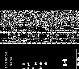
After hours of code cleaning, patching and bug fixing our first “runs” were not that satisfying:
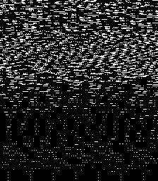
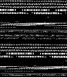
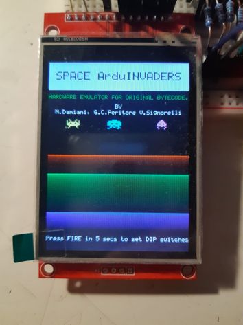
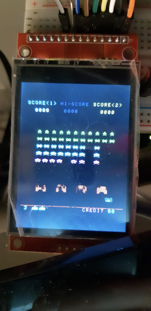
but anyway those pixels shown some logic disposition, and so, bug fix after bug fix, things started to go real better:
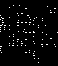
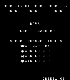
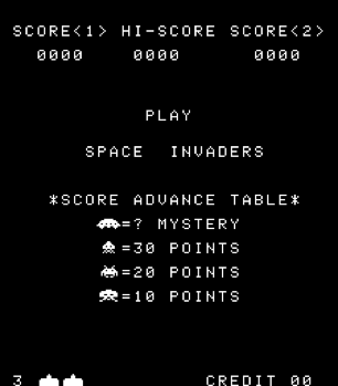
and at least it worked !
But everything was outrageously slow, collisions did not work, the video flickered badly, we had no audio and controls weren’t working. Still a lot had to be done !
Debugging
Our first attempts were not encouraging. Everything was really really slow. We had to do something. We optimized everything, removed any third party library, tried to reduce the number of SPI cycles used to control the display, used unions to access registers easily in 8 and 16 bit modes, access I/O directly, used O2 and O3 compiler optimizations, but it was still too slow… and we started to think that the hardware was too tiny for the project.
Any optimization we made, even “smart” ones, the performances didn’t get any better…
But sudden we noted that the timing was seeming really strange, like when an interrupt is called too often, and the problem was there ! Gotcha ! We were just calling another interrupt while the previous one was running.
It was anyway not the only problem… why the laser does not kill the martian and flies through it ?
When we moved video RAM into the display RAM we didn’t think about collisions. Data had to be reread from the display and this brings more wasted cycles (1 game pixel, represented in 16 bit, 3 bytes to be transferred via SPI). But since we did a lot fo optimizations we had lots of “spare” cycles, so many to be able to code also the color version, emulating the transparencies.
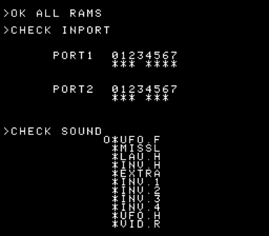
Test ROM !
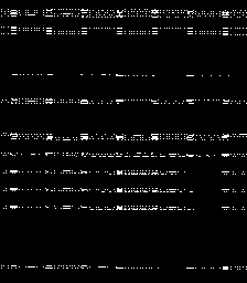
After a lot of debugging the emulation was so detailed that we could run also the so called “test ROM”. The “test ROM” is an EPROM that replaces the H EPROM on the mainboard. Using the “test ROM” proved useful debug sound generation and help on I/O testing.
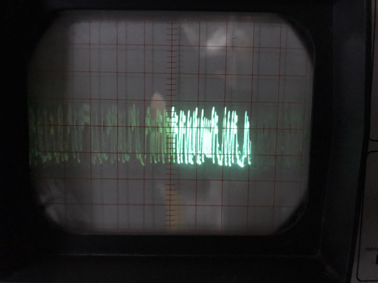
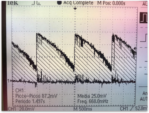
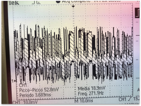
The following grabs are the output of the test ROM.
Audio emulation
The original audio board
The sound board of Space Invaders was almost as big as the main board and had lots of analog components. Probably it was too expensive to work in the eighties with samples or dedicated CPUs, when fast timers were not available. The board was based on divisors, noise generators and used a Texas Instruments SN76477 sound generation circuit, which was used mostly for bitonal sirens. Moreover there were several operationals used as filters and envelope generators, and oscillators like NE-555 and NE-556 timers. The board hosted also a 18 stage shift register called CD4006 and used as random generator.
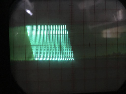
Sound emulation
Owing to limited available resource in our emulating hardware the sound emulation couldn’t be based on samples, sound mixing or tecniques consuming lots of CPU cycles. We had to avoid any form of loop, for, or cycles that may hog the CPU. Moreover we hadn’t 10 pins for the (6+4) sound effects. So: few pins, no loops or delays, no external components, scarce memory what could we (Maurizio) do ?
Base everything on PWM with a 24 KHz timer with real-time generation of waveforms based on subroutines dedicated to the single sound effect ! We generated 8 bit samples on-the-fly and it worked !
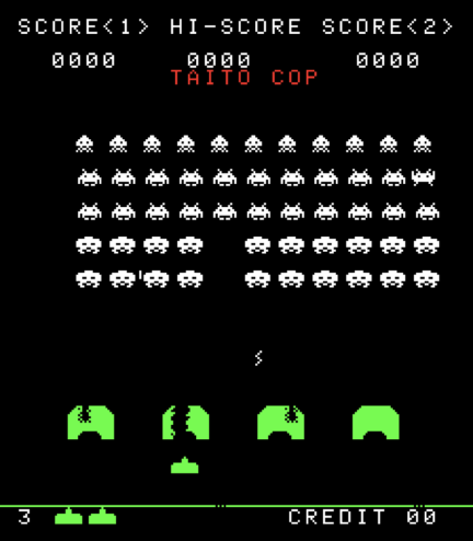
More “features” – Easter egg and Tilt mode
While browsing on various resources available on line we read about an easter egg hidden in the game. According to what was reported on https://computerarcheology.com/Arcade/SpaceInvaders/ during the “Demo mode” you can press at the same moment L+R+Fire+2P Start and soon after L+Fire+1P Start to get a “TAITO COP” label appear on the screen. Being an emulation which runs the original byte code the trick works as depicted in the following image.
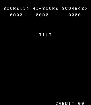
The original cabinet, as it was a sort of logical continuity with the flipper world, had a pendulum used as on oscillation senso to “Tilt” the game in case of excessive movement of the cabinet. Since we did not have a specific “input” to connect to a “tilt” pin on the emulator we emulated. You can “tilt” the game by pressindg Credit and subsequently pressing at the same moment 1P Start + 2P Start.
The game had also a “Cocktail mode”, in which it was arranged under a transparent table, with separate controls for the two players, and flipping vertically the screen towards the active player. We did not emulate that mode in order to not duplicate the controls (left, right, fire).
Tricks
When the first coin-ops appeared in Italy someone noticed that electrostatic discharges were able to do strange things to the arcades. For example on one of the games a spark on the coin acceptor could vertically flip the image.
One of us tried an electric lighter for kitchen on the coin acceptor of Space Invaders discovering that each spark granted a coin credit ! And we discovered, and later verified in the emulator, that any coin inserted after the 99th was lost !
The feature anyway affects not the original Japanese Space Invaders machines but only the cabinets produced in Italy on license. Thanks to Carlo Santagostino for this clarification. Carlo reports also that the Italian version is modified and faster than Japanese and American versions because in Italy there were complaints about the excessive duration of the matches.
Last feature (added) – The screen dumper
At the end of the project we were really tired (we had to finish it in time for OUAS 2019) but even if the program uses 99% of the space available for programs we included an useful feature.
You can press at the same time 1P Start + 2P Start to have on the serial monitor a screen dump in BMP image file format (1 bit/pixel).
What we learned from this project
- There are people who make thinks that tens of years later are able to give us astonishment and deep emotions
- Time is never enough… find it anyway to pursue your passions
- It’s hard, but if you keep on you can reach your goals… in time !
- A good friend it’s the best thing and making a team helps you to go on and avoid stalling
- The OUAS group energy is special !
Many thanks to
We want express our gratitude and thanks to a lot of information sources, and in particular to:
- Tomohiro Nishikado for being able to create this breakthrough arcade in 1977
- https://computerarcheology.com/Arcade/SpaceInvaders/
- http://www.righto.com/2017/04/reverse-engineering-76477-space.html
- http://www.outerworldarcade.com/arcade/
- https://www.classicgaming.cc/classics/space-invaders/sitemap
- http://www.walkofmind.com
- Giovanni Bajio, emulator expert, for his jumptable suggestions
- Carlo Santagostino, videogames history expert, for his contributions
![]()
https://www.facebook.com/onceuponasprite/

And now ? Next steps…
In the next blog posts you’ll find:
- The emulator source code, which can be compiled on the ArduinoIDE or on VSCode/PlatformIO
- Electric schematics of the emulator circuit and instructions to get everything up and running